That part of the earth fault loop impedance which is external to the circuit under consideration. For the supply cable it will be the impedance external to the installation. For other circuits, it is the sum of the impedance of the circuits on the supply side of the circuit under consideration and the impedance external […]
Z2 – That part of the earth fault loop impedance which comprises the impedance under earth fault conditions of the circuit protective conductor (cpc) of the circuit under consideration.
Z1 – That part of the earth fault loop impedance which comprises the impedance under earth fault conditions of the line conductor of the circuit under consideration.
An uninterruptible power supply (UPS) is used to maintain the supply to an essential service duringmains supply outages. On loss ofmains supply,a storage device in the UPS (battery) continues to power the connected load.
Uo Nominal line voltage to earth. Assumed to be 230 V for grid connected systems.
A system having one point of the source of energy directly earthed, the exposedconductive-parts of the installation being connected to earth electrodes electrically independent of the earth electrodes of the source.
A system having one or more points of the source of energy directly earthed, the exposedconductive-parts of the installation being connected to that point by protective conductors.
Where circuits are grouped, there are two availablemethods of calculating the rating factor Cg to be applied: [BS7671:2018,Appendix 4,5.1.2:Equation 2] [BS7671:2018,Appendix 4,5.1.2:Equation 3,4]
Relates to the ability of the soil, in which the cable is installed, to conduct heat energy away from the cable. The rating factor Cs is applied in cable sizing calculations to account for different soil thermal resistivities. For cables with Installation Methods 70 to 73, the values of Cs are found in BS7671:2018, Table4B3. […]
AResidual Current Device (RCD) is amechanical switching device or association of devices intended to cause the opening of the contacts when the residual current* attains a given value under specified conditions. *Residual Current is the algebraic sum of the currents in the live conductors of a circuit at apoint in the electrical installation.
Rating factors are divided into the nominal rating of the circuit protective device (In) to determine theminimum current-carrying capacity (Iz) of a cable in a circuit. For example:Iz = In/(Ca x Cg x Cc x Ci x Ch)Rating factors:Ca –ambient temperatureCc –buried installation methods 70 to 73 (Cc = 0.9)Cd –for depth of burialCf –BS3036 […]
Value of current used for specification purposes,established for a specified set of operating conditions.
Power factor is the ratio of the resistance (R) and impedance (Z) in a circuit, that is:Power factor = cos ∅ =R/Z
Themaximum value of earth fault loop impedance (Zs) that will allow the protective device in a circuit to disconnect an earth fault within the prescribed time. Example: if themaximum earth fault disconnection time for a circuit is 0.4 s and a fault current Ia = 320 A is required to operate the circuit protective device […]
Factors for conductor materials from BS7671:2018,Table43.1. Different values are given for different types of conductor and insulatingmaterials. k2s2 used in adiabatic calculations gives the short-time withstand of a conductor in A2s.
Iz The current carrying capacity of a cable under the defined installation conditions. This is the effective rating of the cable after the relevant rating factors have been applied, i.e.,Ca, Cg,etc.
Ir The adjusted overload rating of an overcurrent protective device, in Amperes.
Prospective Fault Current (Ipf) is the value of overcurrent at a given point in a circuit resulting from a fault of negligible impedance between live conductors having a difference of potential under normal operating conditions,or between a live conductor and an exposed-conductive-part. Or, the calculated fault current at a particular point in the network. The […]
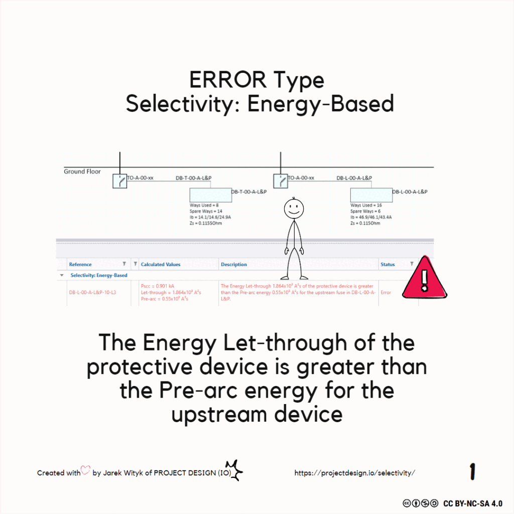
I2t The energy let-through of a device in A2s. The total amount of energy let through by a protective device for a given level of fault current at a stated voltage.
The presence of harmonic content in the line conductors of a three-phase and neutral circuit can give rise to excessive levels of load current in the neutral conductor.
Equipment designed to be fastened to a support or other wise secured in a specific location.
A circuit connected directly to current-using equipment, or to a socket-outlets or other outlet points for the connection of such equipment.
Acircuit condition in which current flows through an abnormal or unintended path. The fault current may flow from line to line (phase fault) or line to earth (earth fault).
It is often not desirable to size each conductor in a distribution system to support the total connected load at that point in the network.Diversity is applied on the basis of the anticipated loadings that are likely to result from all loads not being connected at the same time.
An assembly containing protective devices associated with one or more outgoing circuits fed from an incoming circuit. In the ProDesign software,a distribution board (DB) may be single-phase or three-phase,and can contain up to 100 outgoing circuits.

Resolving Selectivity Issues in Electrical Design Free Trimble ProDesign Introduction Training Course Click the button below for more details: ProDesign Course Selectivity is achieved where,under overcurrent conditions, the protective device nearest the fault operates rather than any protective device on the supply side of it,ensuring that an overcurrent condition will be disconnected without disruption to […]
Circuit Protective Device rating,or ‘In’ in Amperes. If the overload setting can be adjusted, then the ‘adjusted rating’ is known as ‘Ir’.
Design current or ‘Ib’ in Amperes.The level of current to be carried by a circuit in normal service.
Themaximum current which can be carried by a conductor under specified conditions (Installation method, temperature,grouping,etc.)without its steady-state temperature exceeding a specified value (for example,90 ºCfor cables with thermosetting insulation).
The rating factor Cs is applied to cable sizing calculations for cable installed in the ground. Its value varies according to the thermal resistivity of the soil in which the cable is installed. See BS7671:2018,Table4B3.


