Prospective Fault Current (Ipf) is the value of overcurrent at a given point in a circuit resulting from a fault of negligible impedance between live conductors having a difference of
I2t The energy let-through of a device in A2s. The total amount of energy let through by a protective device for a given level of fault current at a stated
The presence of harmonic content in the line conductors of a three-phase and neutral circuit can give rise to excessive levels of load current in the neutral conductor.
Equipment designed to be fastened to a support or other wise secured in a specific location.
A circuit connected directly to current-using equipment, or to a socket-outlets or other outlet points for the connection of such equipment.
Acircuit condition in which current flows through an abnormal or unintended path. The fault current may flow from line to line (phase fault) or line to earth (earth fault).
It is often not desirable to size each conductor in a distribution system to support the total connected load at that point in the network.Diversity is applied on the basis
An assembly containing protective devices associated with one or more outgoing circuits fed from an incoming circuit. In the ProDesign software,a distribution board (DB) may be single-phase or three-phase,and can
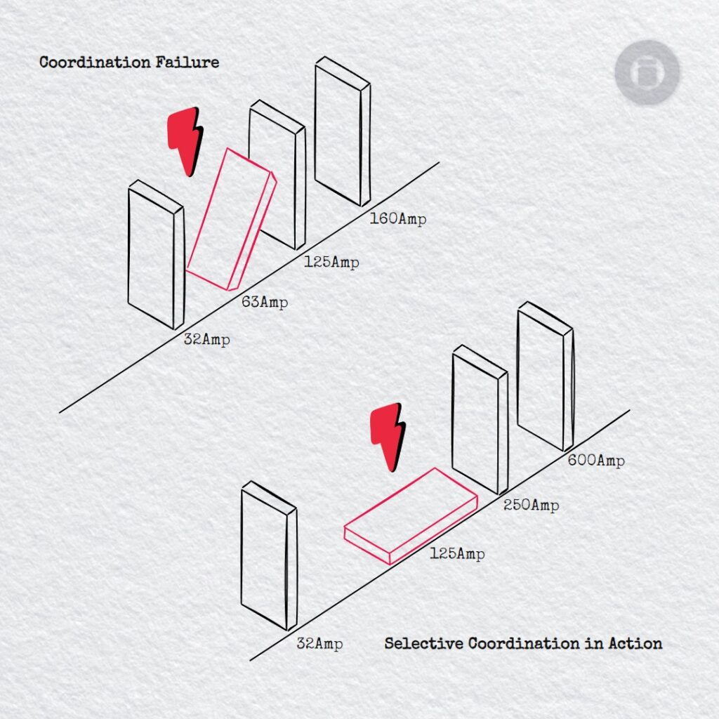
Resolving Selectivity Issues in Electrical Design Free Trimble ProDesign Introduction Training Course Click the button below for more details: ProDesign Course Selectivity is achieved where,under overcurrent conditions, the protective device
Circuit Protective Device rating,or ‘In’ in Amperes. If the overload setting can be adjusted, then the ‘adjusted rating’ is known as ‘Ir’.
Design current or ‘Ib’ in Amperes.The level of current to be carried by a circuit in normal service.
Themaximum current which can be carried by a conductor under specified conditions (Installation method, temperature,grouping,etc.)without its steady-state temperature exceeding a specified value (for example,90 ºCfor cables with thermosetting insulation).
The rating factor Cs is applied to cable sizing calculations for cable installed in the ground. Its value varies according to the thermal resistivity of the soil in which the
A fuse or circuit-breaker providing overload and fault current protection.
Atype of single-phase board for the control and distribution of electrical energy, principally in domestic premises. In the ProDesign software,a consumer unit (CU) can be split into three sections,each with
Aperson who possesses sufficient technical knowledge, relevant practical skills and experience for the nature of the electrical work undertaken and is able at all times to prevent danger and,where appropriate,
Acircuit protective conductor (CPC) connects exposed-conductive-parts* of equipment to themain earthing terminal. *Conductive part of equipment,which can be touched and which is not normally live,but which can become live when
Ci Rating factor used for calculating theminimum required cable size for cables run in thermal insulation. See BS7671:2018 Table52.2.
Ch Rating factor used for calculating theminimum required cable size in the presence of harmonic currents.See BS7671:2018,Appendix 4, section 5.5.
Grouping rating factor used for calculatingminimum required cable size. For cables installed in air, values for this factor are given BS7671:2018,Tables4C1,4C4,4C6.For ground installations, values are given in Table4C2. Grouping a
The rating factor Cf = 0.725 is applied to cable sizing calculations for any circuit protected by a semi-enclosed fuse to BS3036.
The rating factor Cd is applied to cable sizing calculations for cable installed in the ground. Its value varies according to the depth of lay installed. See BS7671:2018,Table4B4. Indicates the
The rating factor Cc = 0.9 is applied to cable sizing calculations for cables installed in the ground (Installation Methods 70 to 73). See BS7671:2018,Appendix 4,Sections3,4 and 5.1.1.
Circuit-breaker manufacturers publish tables showing combinations of pairs of circuitbreakers, one upstream,one downstream,where the downstream device can be used at a location where the prospective fault current (Ipf) is higher
k2s2 its an Energy withstand of cable in A2s. For example,a cable with a withstand of 12 x 104 A2s, can sustain without permanentdamage,a fault current of 1,000 A for
Ambient temperature rating factor used for calculating theminimum required cable size. For cables installed in air, values for this factor are given in BS7671:2018 Table4B1.For ground installations, values are given
IWE-S1-IWE- E8_Breaking Capacity of MCCB What is Breaking Capacity (kA) Breaking capacity, often referred to as short-circuit breaking capacity, is one of the most critical specifications of a protective device.
Protection against electric shock under fault-free conditions;use of barriers,placing out of reach,and so forth.
The temperature of the free air surrounding a cable,or in the case of cables installed in the ground, the temperature of the surrounding soil.For an enclosed method such as ‘In
Adiabatic checks are required to determine whether conductorsmight be damaged by the thermal effects resulting from the level of calculated fault conditions.