All case studies
Case Study

Hospital Diagnostic and Inpatient Unit
Hospital
Complete
Overview
A 7,793 m² modular diagnostic and inpatient facility at Frimley Park Hospital. Project Design (IO) delivered the electrical coordination across four floors, from diagnostics and wards to the rooftop plant room.
Project data
- GFA
- 7,793 m²
- Ground Floor: Diagnostic and Mammography Departments with 2 MRIs, 3 CTs, 2 Gamma Cameras, 2 Mammography units, and 2 Ultrasound Rooms.
- First Floor: 38-bed Decant Ward with 22 single bedrooms (each with an ensuite) and 4 four-bed bays.
- Second Floor: 36-bed Respiratory and MADU Ward with 12 Very High Dependency Single Rooms (each with an ensuite), 12 step-down single rooms (each with an ensuite), and 3 four-bed bays.
- Third Floor: Plant room.
Project Design (IO) was appointed to coordinate the electrical services for this new modular hospital building - covering electrical, fire, nurse call and security systems through to construction-issue drawings.
Key tasks- Containment Coordination
- Plantroom Coordination
- Vertical Distribution
- Coordination of 1600Amp Bus-Bar incoming supply
- Coordination of specialist services
- Coordination of Lighting and Small Power Services
- Provision of construction drawings (shop drawings)
Quantities
- 723 Lighting Devices
- 1,880 Lighting Fixtures
- 836 Data Devices
- 732 Security Devices
- 662 Nurse Call Devices
- 1,748 Fire Alarm Devices
- 6,558 meters of Containment
Project overview
- Project name
- Frimley Park Hospital
- Project code
- FPH035
- Location
- Frimley Park Hospital, GU16 7UJ
Project participants
- Client
- Contact us to disclose
- MEP contractor
- Contact us to disclose
- MEP consultant
- Contact us to disclose
- BS manager
- Contact us to disclose
- Mechanical coordinator
- Contact us to disclose
- Other participants
- Contact us to disclose
Challenges & solutions
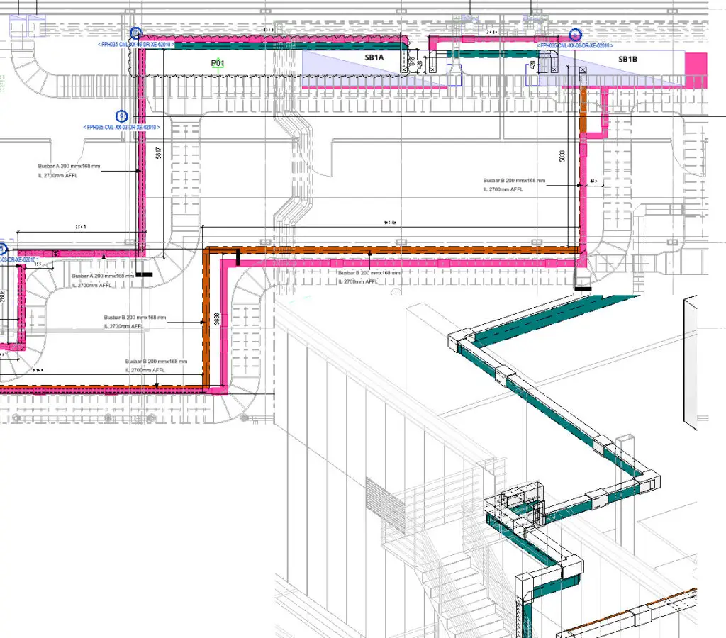
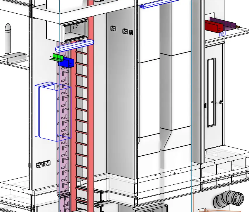
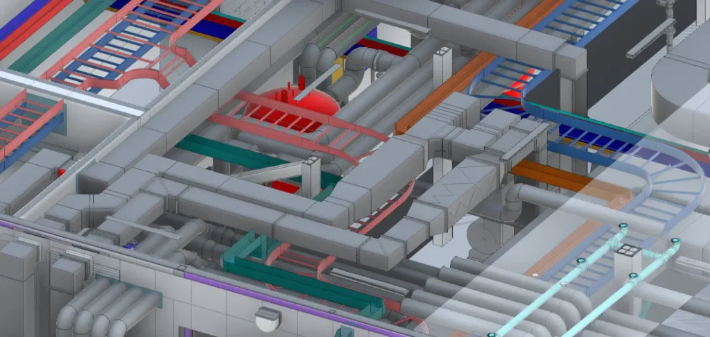
Incoming Supply 1600Amp Busbar
Challenge
The incoming LV supply was served via a cast resin busbar system 1600 Amp, provided by the manufacturer as a 3D model. Once imported and aligned to the project coordinates, the busbar model revealed number of critical issues: for example the ground floor section was too short to reach the intended termination point, and the busbar clashed with structural elements within the second floor plantroom. These issues had not been identified by the manufacturer.
Solution
By importing and coordinating the manufacturers 3D busbar model against architecture and structure, we detected all issues. We then adjusted the route and dimensions in Revit, confirmed fixing and support locations, and issued a coordinated model and setting out information back to the manufacturer ahead of fabrication.
Vertical Distribution
Challenge
The consultant's design did not allocate sufficient riser space for the electrical submains and distribution boards, and the electrical and mechanical risers were not aligned. This constrained the available cable routes and began to drive changes to surrounding services and the architectural layout.
Solution
Late in the design, insufficient electrical riser space meant the original vertical distribution could not be built. By replanning the riser strategy, creating new vertical routes and repurposing existing mechanical risers, we recovered enough space for submains and distribution boards and agreed a coordinated, buildable riser layout across all disciplines.
Plantroom Coordination
Challenge
The MEP model carried generic mechanical plant at the end of RIBA Stage 3. When the actual plant selections were confirmed, the plantroom layout had to be substantially redesigned, driving extensive recoordination and adding approximately 12 weeks to the programme.
Solution
We re-engineered the electrical scope to suit the revised plantroom layout, re-routing the cast iron busbars, cable ladder and electrical risers through the updated mechanical plant arrangement. By sequencing our design changes to track the rolling mechanical redesign, we maintained alignment between electrical and mechanical coordination throughout the extended Stage 3 to 4 transition, avoiding an additional round of late rework once the plant layout stabilised.
Outcomes
Electrical systems coordination
Coordinated lighting, power, fire alarm, nurse call and security across the building into a single federated model.
Diagnostic equipment
Coordinated the electrical provision for MRI, CT, Gamma Camera and mammography suites, including their specific power and containment requirements.
Efficiency
Improved maintenance access through coordinated containment and plant routing.
Space management
Resolved the riser and distribution-board space allocation early, protecting both the programme and the architectural layout.
Analysis
The project was modelled and coordinated entirely in Autodesk Construction Cloud, with bespoke Revit families built for the specialist clinical equipment and fittings. Coordination ran in two main phases: an initial WIP and P01 issue, followed by a substantial revision once the mechanical plant was confirmed. That redesign increased the containment coordination effort by more than 50%, concentrated in the containment routes, vertical risers and small power — reflecting how much downstream electrical work depends on the mechanical plant being fixed early. Throughout, the model was kept clash-free through routine checks, allowing issues like the busbar and buffer-vessel clashes to be resolved before they affected adjacent services or the programme.
Current status
In Operation
Certain project details are confidential and shown as "Contact us to disclose". Figures and outcomes are presented with project context only.