The PD_ELE_Electrical-Equipment_Generator-M237_v24 was developed because no existing Revit family supported this specific generator set, and it contains parameters to manage key equipment, dimensional, and project information within Revit.
In this guide, we will walk through what the family can do, how the family was built, key parameters, how to use it in a project, design decisions, testing and limitations.
Key Features:
✅ Project-Specific Geometry
Geometry developed from the available M237 details and manufacturer/project information.
✅ Coordination-Ready Footprint
Represents the equipment footprint and major projections for coordination within the Revit Model.
✅ Detailed External Components
Key external components modelled for identification, visual representation, and coordination.

The PD_ELE_Electrical-Equipment_Generator-M237_v24 was developed to provide an accurate, configurable representation of the specified equipment in Revit.
✅ Accurate Equipment Representation:
Recreates the overall form, dimensions and major components of the M237 generator, providing a more representative alternative to generic placeholder geometry.
✅ Improved Coordination:
Represents the physical footprint and major projections to support coordination with surrounding equipment, structures, services and access requirements.
✅ Appropriate Level of Detail:
Includes key components required for equipment identification and coordination while avoiding unnecessary geometric complexity.
✅ Project-Specific Solution:
Developed from the manufacturer and project information where no suitable existing Revit family was available for the specified generator set.
The M237 family was developed using the drawing provided by Tarplett Generator Services (TGS) LTD as the primary source of dimensional and equipment information.
The generator was developed in stages, starting with the primary enclosure and overall form before creating more detailed components as separate Revit families and incorporating them into the completed generator family.
01 – Source Information & Planning
Development of the M237 family began with a review of the drawings provided by TGS, which were used to understand the generator’s overall geometry and component arrangement.
Key information was identified from the available views, including overall dimensions, enclosure profile, base and supports, ventilation areas, lifting points and the arrangement of major external components.
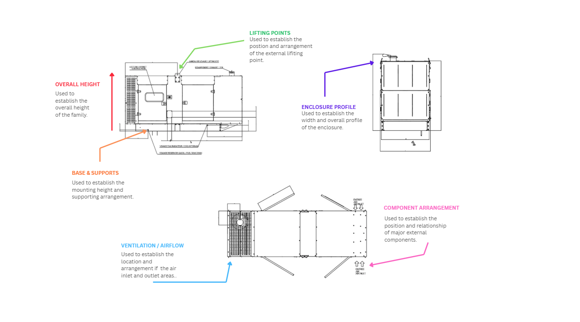
These drawings formed the basis of the modelling process and helped determine which features required representation for equipment identification and spatial coordination.
02 – CAD Import & Initial Set Up
Relevant CAD views were imported into the Revit Family Editor and positioned to provide aligned references during modelling.
The front, side and plan views allowed the generator to be viewed consistently from multiple directions, helping establish the relationship between its overall form and individual components.
The CAD views remained as modelling references while the generator itself was recreated using native Revit geometry.
03 – Main Generator Structure
With the reference information established, modelling began with the primary generator structure.
The main enclosure and base were created first to establish the M237’s overall size, footprint, and height. Building these larger forms first provided a framework for the more detailed components added later.
At this stage, the focus was on achieving the correct overall form and proportions rather than modelling smaller external details.
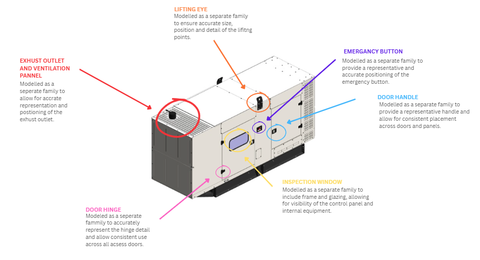
04 – Component Family Development
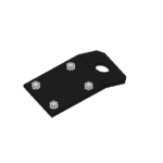
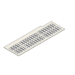
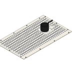
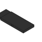
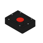
Several external components were developed as individual Revit families rather than modelling all of the detail directly within the main generator family.
Each component was reviewed across the available front, side and plan CAD views to understand its width, depth, and overall form before being recreated using native Revit geometry.
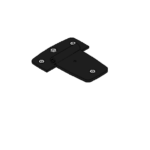
Developing these elements separately provided greater control over detailed and repetitive geometry, particularly for components used multiple times across the generator, such as handles and hinges.
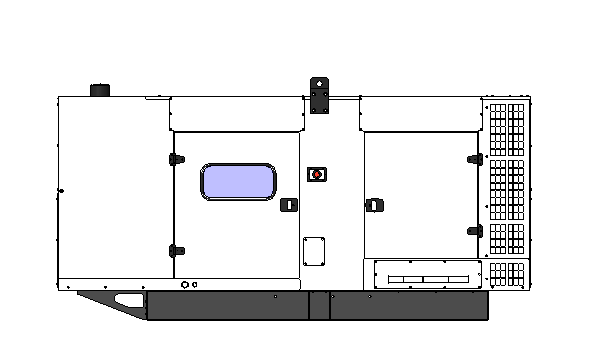
05 – Bringing the Components Together
Once completed, individual component families were loaded into the main M237 family and positioned relative to the primary generator structure.
The original CAD references were used to check each component’s placement and alignment, while the developing family was reviewed in 3D to ensure the overall arrangement remained representative of the source information.
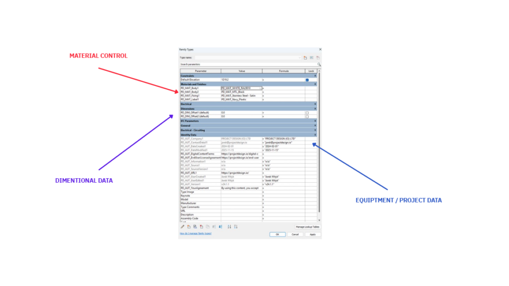
The PD_ELE_Electrical-Equipment_Generator-M237_v24 contains a range of parameters used to manage the family’s materials, dimensional controls, and equipment/project information.
Materials & Finishes
Controls material assignments for key elements of the generator, allowing the appearance of components to be managed consistently within the family.
Dimensions Data
Contains dimensional controls used to position and offset specific geometry within the family.
Equipment / Project Data
Stores information used to identify and manage the generator within a project, including equipment references, manufacturer information, descriptions, and other project-specific data.
Identity Data
Records information relating to the file’s source, author, version and associated digital content.
The M237 family provides a project-ready representation of the specified equipment. Once approved for use, you can load the family into a Revit project, position it according to the project design, and use it for coordination and documentation.
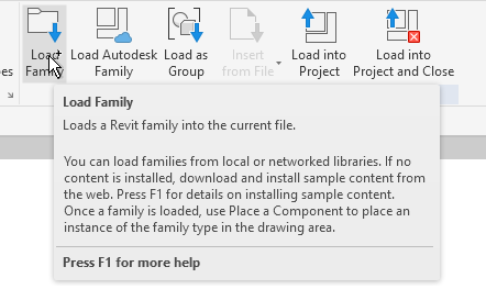
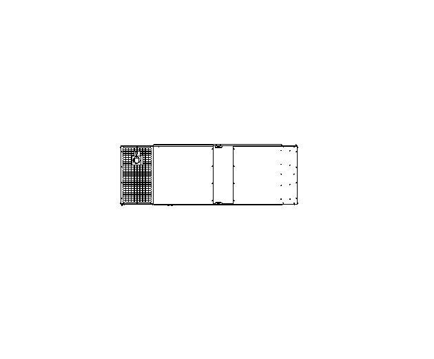
01 – LOAD
Load the approved family using Insert → Load Family
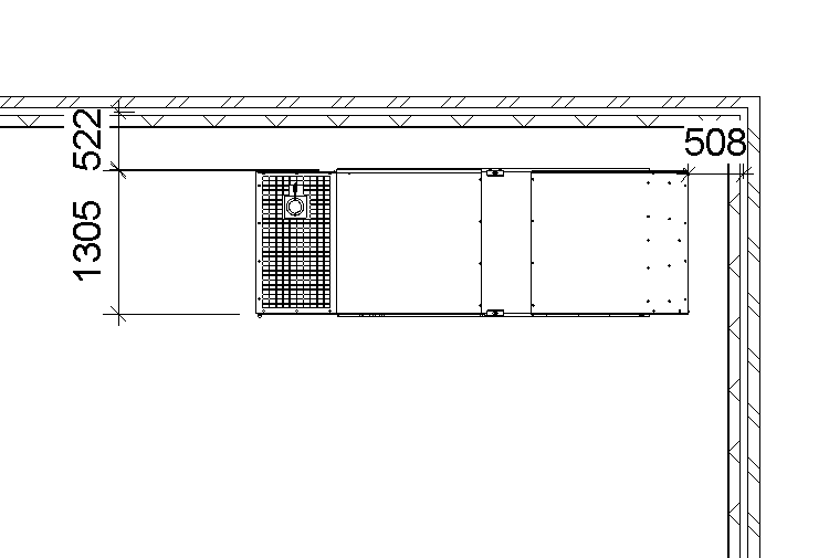
02 – PLACE
Position and orient the generator according to the project design.
03 – COORDINATE
Review the equipment footprint and major projections against surrounding elements.
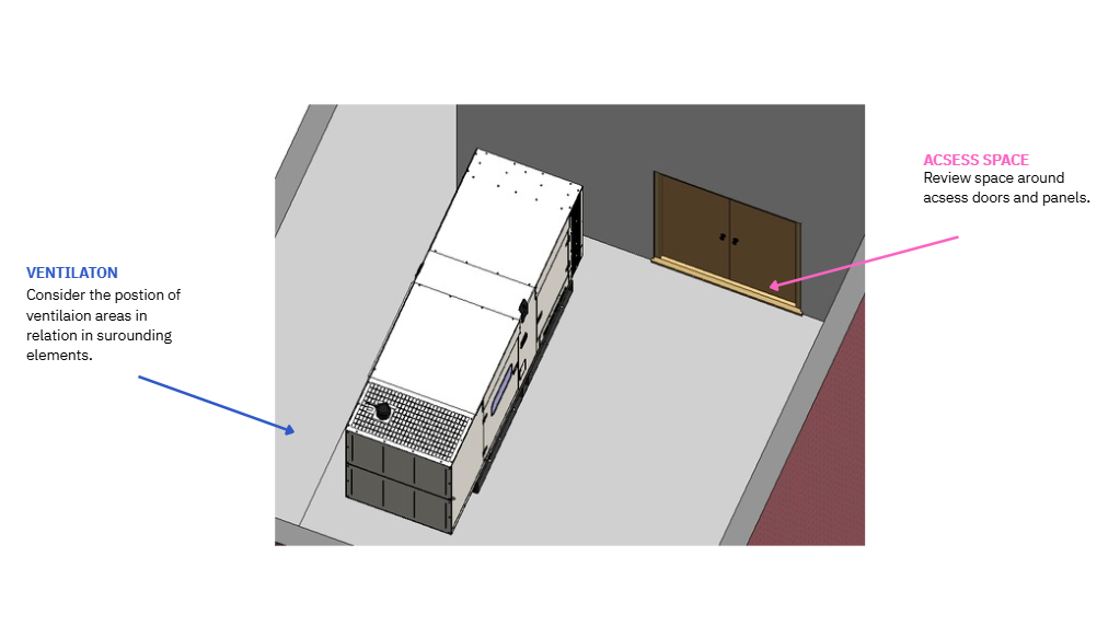
04 – REVIEW ORIENTATION AND ACCESS
Review the generator orientation and consider the placement of access doors, ventilation areas, and other external components relative to the surrounding space.
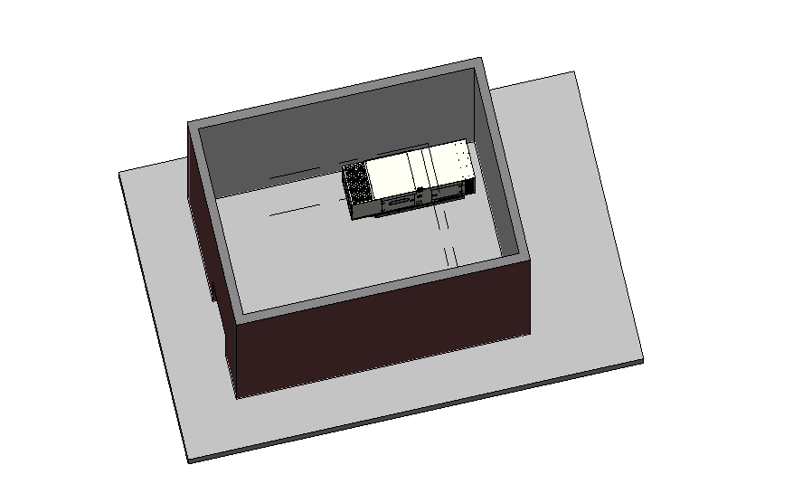
05 – REVIEW IN 3D
Review the generator in 3D to confirm its overall placement and relationship with the surrounding model.
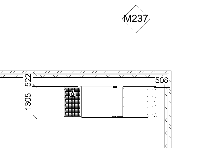
06 – DOCUMENT
Use the family within relevant schedules, tags and project documentation.
The PD_ELE_Electrical-Equipment_Generator-M237 provides a project-specific Revit representation of the specified generator, developed from drawings provided by TGS.
The completed family should be reviewed within the project environment to confirm its dimensions, component arrangement, equipment information and graphical representation before being approved for use.
This family represents the M237 generator configuration and should not be modified to represent alternative equipment without suitable supporting information.
🔗 Download the latest version here: