Key takeaway: Indicator for generators and smoke-control systems (commonly referred to as ‘mimic panel’, often marked “ESP – Emergency Stand-by Power Identification Panel”) should be provided at the main fire-alarm panel and/or fire-service interface points.
In practice, when provided, it should connect the Generator Control Panel to every Automatic Transfer Switch (ATS) and the Building Management System (BMS), where monitoring is required using fire-resistant cabling that matches the BS 8519 categories. Remember that each system must be project-specific; therefore, the designer remains free to choose the monitoring philosophy, provided the Fire Strategy demonstrates equivalence. Cat 2 fire-resistant cable is normally accepted by BSR/FRS, where ATS contacts are monitor-only (no control function).
This guide explains:
What a mimic panel is and how it is annotated on layout and schematic drawings
When a mimic panel is mandatory – and when it is optional
Which generator signals must appear on the mimic panel.
Where to show voltmeter and ammeter readings to comply with BS EN 12101-10:2005 §6.3.2 and BS 8519:2020 §6.3
Worked compliance checklists and example mimic panel datasheet.
All recommendations presume UK practice; no overseas codes are referenced.
| Element | Typical Drawing Symbol | Purpose in Life-Safety Context |
|---|---|---|
| ESP Mimic Panel | Square with “ESP” tag on floor plan; dashed link to CIE on schematic | Brigade front end for generator, smoke control, firefighting lifts |
| CIE (Control & Indicating Equipment) | Rectangle “CIE” | Main fire alarm panel (BS 5839-1) |
| ATS Status LED Block | Triangle or three stacked arrows | Shows mains healthy, generator running, generator fault |
A mimic panel is a hard-wired, low-voltage fascia that repeats essential generator or smoke-control signals at the point where the fire-rescue service first assumes control. It is not a PLC HMI or BMS screen.
| Location | Designated Fire-Fighting Access Point (FFAP)? | Fire-service control of life-safety systems from this point? | Continuous staff presence? | Visual indication should be provided? |
|---|---|---|---|---|
| Main fire-control room | Yes | Yes | Yes | Yes |
| Ground-floor core entrance | Yes | Yes | No | Yes |
| Underground car-park ramp | No | No | No | No |
BS 5839-1:2025 §22.1 requires the main control & indicating equipment “close to the entrance likely to be used by the fire-rescue service”[1]. Although the BS 5839-1 §22.1 does not mention ‘mimics’, a mimic is one way to satisfy §6.3 of BS 8519 (remote indication) – note that ‘Should’ in a BSI Code-of-Practice allows an engineered alternative if it is justified and agreed; it is not an absolute legal requirement.
Typically, however, if the entrance is not an FFAP, a mimic becomes optional.
BS 8519:2020 standard adds a second sentence: “A voltmeter and ammeter indicating the total load on the generator shall also be provided.” [3]
The standard does not prescribe the location. Placing the instruments on the generator control panel satisfies the clause. UK project reviews show this arrangement on >90% of schemes without objection from approving authorities.
| Signal | Type | Comment |
|---|---|---|
| Mains available | Digital IN | 230 V relay or clean contact |
| Generator available | Digital IN | From genset breaker auxiliary |
| ATS position (on mains/on gen) | Digital IN | Two-pole feedback for SIL 2 equivalence |
| ATS common fault | Digital IN | Fault/fuse fail on ATS controller |
| Modbus status (optional) | RS-485 | If manufacturer provides |
BS 8519 does emphasise dual/diverse routing (clause 7) and recommends that each critical circuit is able to survive fire; it does not expressly ban daisy-chaining low-current monitoring contacts between ATSs. However, many consultants insist on running individual circuits when the loss of a single cable would disable more than one life-safety load [3].
| Circuit | Standard Clause | Cable Category | Example Cable | Min. Survival (min) |
|---|---|---|---|---|
| Mimic LED feeds | BS 8519 Table 1 | Cat 2 | 2 × 1 mm² FP200 Gold | 60 |
| ATS control & feedback | BS 8519 §11 | Cat 3 | 4 × 1.5 mm² FP600S | 120 |
| Generator CT/PT loops | BS 8519 §11 | Cat 3 | MICC 4 × 2.5 mm² | 120 |
BS 8519:2020 clause 15 (Cable installation practice) states that cables should be installed following the cable manufacturer’s recommendations [3] for fixing intervals. The standard doesn’t mandate a universal spacing.
A 300 mm spacing requirement specifically applies to:
Inverted cable management systems – as confirmed by the BEAMA guidance which states: “Where cable tray or ladder is used in an inverted orientation, cable fixings must be used with the spacings defined in Table 2”[4] – which shows 300 mm for cables up to 15 mm diameter.
Fire alarm cables on inverted tray – as discussed in the Voltimum Q&A: “We are electrical contractors installing soft-skinned fire alarm cables on inverted cable tray. At the moment, we are fixing the cable at 300mm centres”[5].
Cables not supported by metal containment – where cables are clipped directly to building fabric, manufacturer recommendations typically suggest 300 mm horizontal/400 mm vertical spacing [5].
| Feature | Requirement | Reference |
|---|---|---|
| LED legends engraved in English | “MAINS ON”, “GEN ON”, “FAULT” | BS 8519 Fig 1 |
| Lamp-test push-button | Momentary, shrouded | FIA CIE Guidance p.9 |
| PSU | EN 54-4, 72 h standby | BS 5839-1 Table 11 |
| Enclosure rating | IP 55, RAL 7035 steel | BS EN 60529 |
| Cable entry | Gland plate underside | BS 7671 18th Ed. |
| Item | Design Stage | Verified (✓) |
|---|---|---|
| FFAP locations confirmed in Fire Strategy | RIBA Stage 2 | |
| Mimic panel only at FFAP | Stage 3 | |
| Generator control panel fitted with V & A meters | Stage 3 | |
| Three mimic LEDs wired via clean contacts | Stage 4 | |
| Each ATS wired back to BMS with Cat 3 or Cat 2 cable[*] | Stage 4 | |
| Cabling routes enclosed 120 min | Stage 4 | |
| EN 54-4 PSU autonomy test certificate | Stage 5 | |
| Cause-and-effect matrix references mimic I/O | Commissioning |
[*] Each ATS wired back to BMS with Cat 3 cable (or Cat 2 where monitor-only, subject to risk assessment).
| Task | Interval | Standard |
|---|---|---|
| Lamp-test and LED visual check | Weekly | BS 5839-1 §44 |
| Simulated mains failure (ATS test) | Monthly | BS 8519 §6.3 Note 3 |
| Generator load-bank test incl. V & A reading | Annual | BS EN 12101-10 Test 12.1 |
| Cable clamp & gland inspection | 3-yearly | BS 8519 §12.3 |
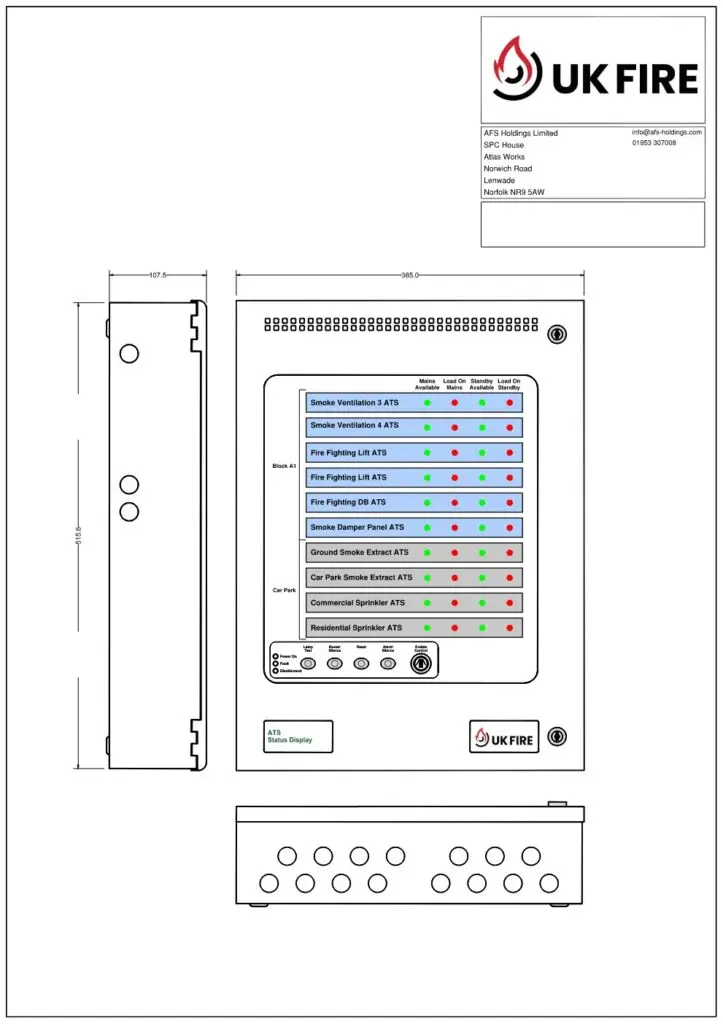
Provide an ESP mimic panel adjacent to the main Control & Indicating Equipment.
The panel shall display, via hard-wired LEDs, Mains Healthy (green), Generator Running (red) and Generator Fault (amber).
Voltmeter and ammeter shall be integral to the generator control panel.
ATS status and fault contacts shall be wired in Category 3 fire-resistant cable to the BMS and mimic panel.
Panel supply shall be 24 V d.c. from an EN 54-4 power unit with 72 h standby.
Enclosure: IP 55, RAL 7035, 1.5 mm steel, minimum 300 × 300 × 150 mm.