You can either follow the instructions below or watch the step-by-step instructions on my YouTube channel by following this link: https://youtu.be/Ma-ydZyqQdQ
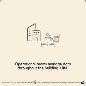
Discover how to create tiltable geometry placeholders for face-based families in Revit, enabling full 3D rotation in any direction.
This is a family agnostic tool- that works with all face-based families
Axis angles used are based on Euler Angle names adapted to match Revit environment.
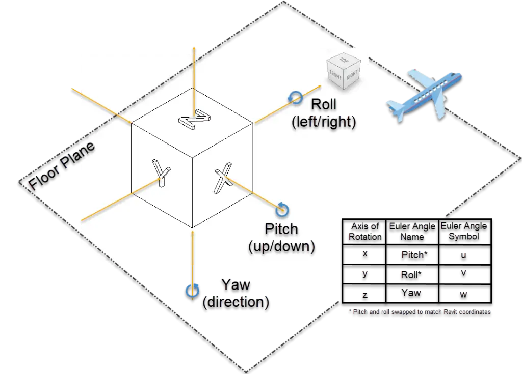

A yaw rotation is a movement around the yaw axis of a rigid body that changes the direction it is pointing, to the left or right of its direction of motion.
PD_GENc_Rotation_YTo rotate a family in three different planes (X, Y, and Z), you need to control each rotation action separately. To do this, you must nest each rotation parameter within the next family, creating at least three levels of nesting. Each level has a host 3D object that is responsible for driving/enabling the rotation. To make this work, each family must be face-based. By using a face-based family as a host and rotating it, your object will move along with it, as it is attached to its face.
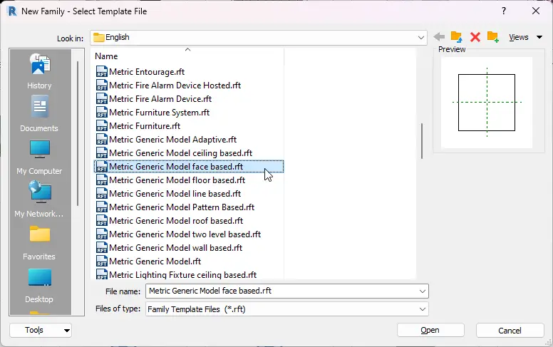
Create a generic model (face-based) named PD_GENc_Rotation_Y
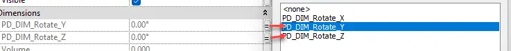
create PD_DIM_Rotate_Y (shared) instance type parameters:
Discipline: Common | Type: Angle | Group parameter under: Dimensions
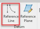
In Elevations/Front, create a reference line and lock one end to both X & Y reference lines – lock the end point of the line
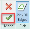
In Elevations/Front, create a Sweep and Pick Path – the newly created reference line. Once Path is picked, accept the selection by clicking the green tick.
Then still in Modify | Sweep select Load Profile
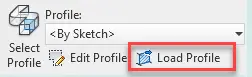
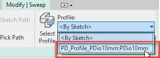
Navigate to the profile file of your choice – I am using the PD_Profile_PDio10mm.rfa
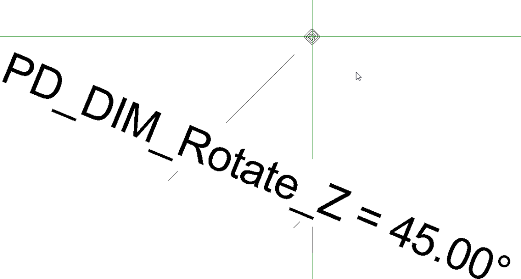
now select the reference line used as a profile and add the Angular dimension
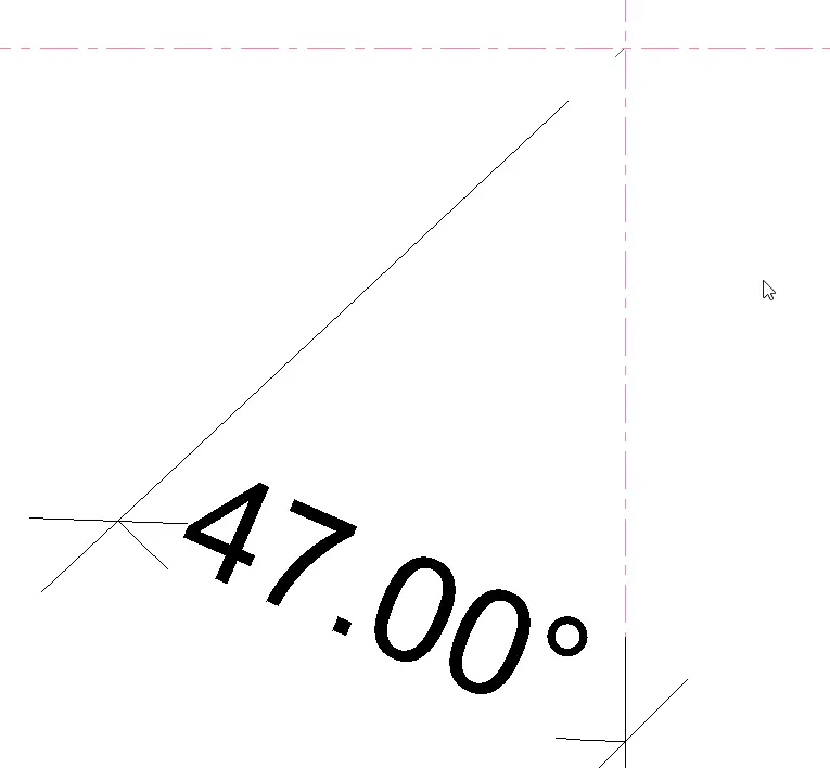
Now associate the new dimension with PD_DIM_Rotate_Y parameter
That’s all you created the first nested family needed to create the rotation base, save it but do not close just yet
PD_GENc_Rotation_YZCreate a new generic model (face-based) named PD_GENc_Rotation_YZ
create PD_DIM_Rotate_Y and PD_DIM_Rotate_Z (shared) instance type parameters:
Discipline: Common | Type: Angle | Group parameter under: Dimensions
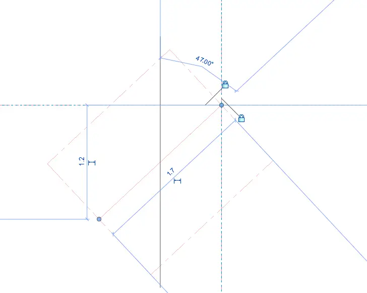
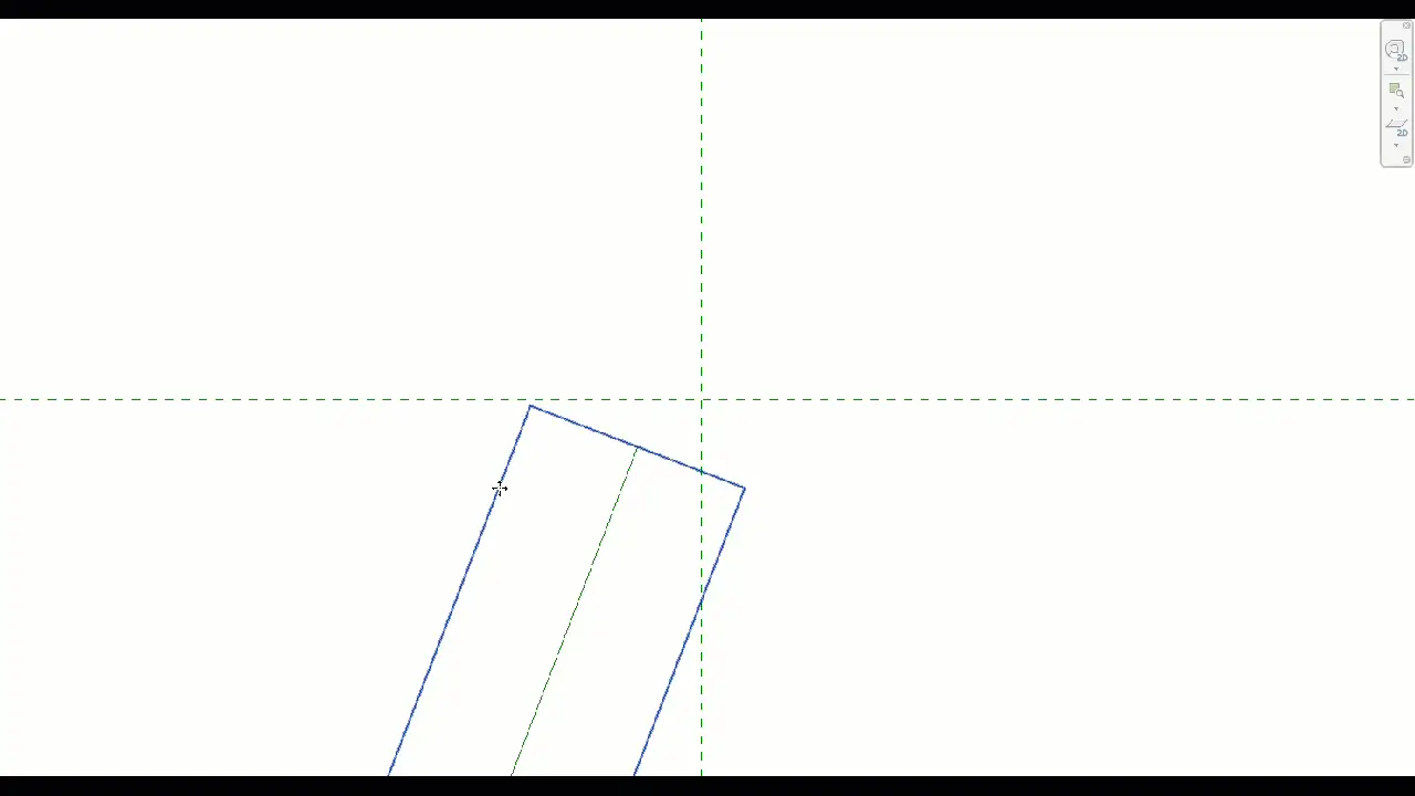
PD_GENc_Rotation_Y and load it to PD_GENc_Rotation_YZOnce loaded go to Ref.Level Floor Plan, and manually rotate it so its easier to add dimension
add the Angular dimension and associate the new dimension with PD_DIM_Rotate_Z parameter
Now select the nested family and associate PD_DIM_Rotate_Y parameters with the PD_DIM_Rotate_Z parameters

That’s all you create the second nested family needed to create the rotation base; save it but do not close it just yet
PD_GENc_Rotation_XYZCreate a new generic model (face-based) named PD_GENc_Rotation_XYZ
PD_GENc_Rotation_YZ and load it to PD_GENc_Rotation_XYZcreate PD_DIM_Rotate_X PD_DIM_Rotate_Y and PD_DIM_Rotate_Z (shared) instance type parameters:
Discipline: Common | Type: Angle | Group parameter under: Dimensions

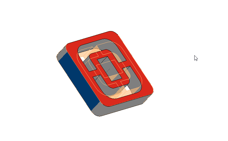
Here you need to create a void sweep object. This will become host to your PD_DIM_Rotate_YZ, and it will allow you to rotate the void third X direction.
PD_GENc_Rotation_YZ
Repeat the steps from PD_GENc_Rotation_Y and create the sweep, but this time it is going to be Sweep Void
First, go to the left elevation and create a Reference line.
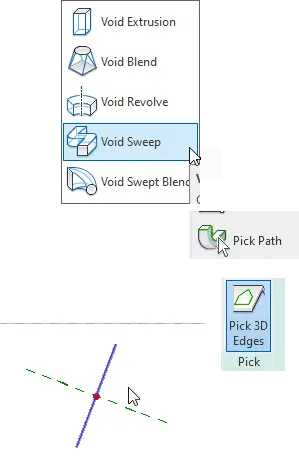
Now go to Create > Void Forms > Void Sweep > Pick Path > Pick 3D Edges > Pick your reference line
Now associate the end of the reference plane with X and Y reference lines; best to hide Ref. Level and the Void Sweep so it’s easier to select
In the left elevation, add the angled dimension and assign to PD_GENc_Rotation_X.
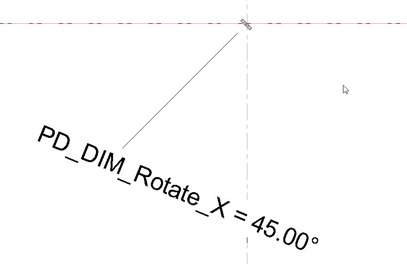
The sweep is used to control the X angle of the PD_GENc_Rotation_YZ, which is hosted on the void face.
Now, unhide all, select your PD_GENc_Rotation_YZ family and Pick New Host; best to do this in 3D; select the TOP Face of the void
Now select the nested family and associate the parameters
PD_GENc_Rotation_X is going to be associated at the next level when the PD_GENc_Rotation_XYZ family is loaded to your target family to be used as rotating host.Last step, Now change the family type to Site, this way you can ensure its hidden and does not mix with any other family types
This is it, you created a geometry placeholder which you can load to a non-hosted model and then use it to host other face based families to rotate them any direction.