
A consistent naming strategy is critical for productivity when working in Revit
Every view, sheet, filter, family, and parameter becomes part of a living dataset. Without clear, predictable naming conventions, you end up with a lot of confusion and wasted time!
This is why with permission of Gavin Crump, I used his naming convention as a base for all parameters in the project template. Its not just a copy of Gavin’s Shared Parameters, but rather evolved version of his idea, adapted to suit electrical discipline.
Open the model and the first thing you’ll see is the Project Dashboard.
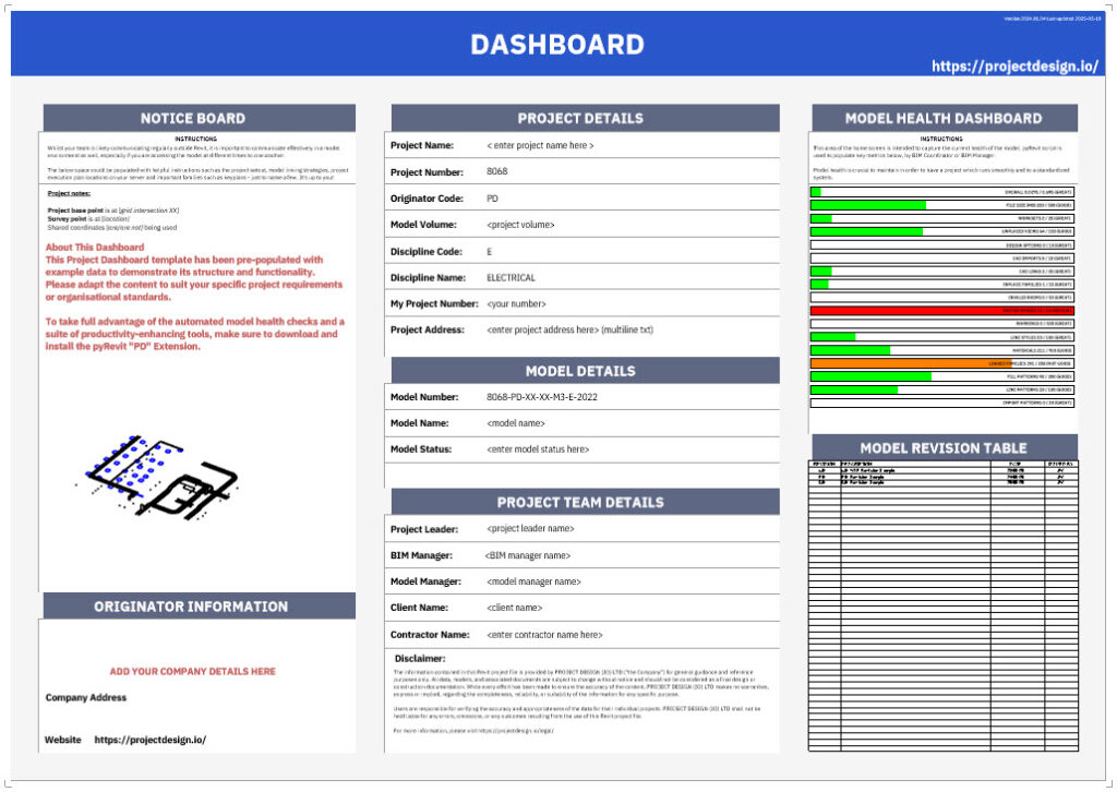
It ships with dummy data so you can see the wiring; swap the placeholders for your own project details and you’re ready to roll.
| Zone | What it’s for | How to edit |
|---|---|---|
| Notice Board | One-liners, site memos, alerts. | Click into the text note and overwrite the sample copy. Keep it short; the board isn’t a novel. |
| Originator Information | Your company name, address, logo if you fancy. | Edit the text fields (or replace the logo image). |
| Project & Model Details | Live read-outs of Project Information parameters (number, name, stage, etc.). | Do not touch the dashboard text; go to Manage ▶ Project Information and update the parameters once—changes ripple to sheets and tags automatically. |
| Model-Health Gauge | Real-time “traffic-light” of warnings, links, view count, etc. | Powered by the family PD_GAN_ModelHealth-Gauge plus the free pyRevit “PD” extension. Install the extension to unlock the automated checks; otherwise the gauge will sit there looking pretty but static. |
| Model Revision Table | Tracks every formal issue of the model or sheets. | Uses Revit’s built-in revision system (View ▶ Revisions). We’ve pre-loaded three naming tracks: C0x — Published (C01, C02…) P0x — Shared (P01, P02…) x.01 — WIP (x.01, x.02…) |
See our cheat sheet: Table 36 – Status and Suitability
Five minutes and your dashboard will look like it was built for this project—because, well, it now is.
This template isn’t just a blank shell—you’re getting a turnkey starter kit that would normally cost a small fortune in add-ons. Everything listed below is wired-in, QA-checked, and ready to drop into real projects.
| Family & Version | Normal List Price | What it gives you | Where it’s used |
|---|---|---|---|
| PD_ELE_Electrical-Equipment_DistributionBoards | £ 24.90 | Parametric DB enclosure, spare-way logic, DIN-rail calc | Drives the sample Distribution-Board schedules |
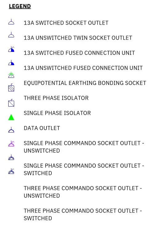
| PD_ELF_Electrical-Fixture_Socket_v22.2.1 | £ 49.90 | UK twin & single sockets, data, USB, | Lighting/Small-Power legends & schedules |
| PD_LTF_Lighting-Fixture_Luminaire-Rectangular_v22.1.3 | £ 49.90 | Recessed/Surface, parametric, any size | Lighting plan, BREEAM sample notes |
Why the price tags?
We’re not being cheeky, just honest. You’re getting around £125 worth of kit, already tested. If that earns the template a second look when the next spec drops… job done.
What it is
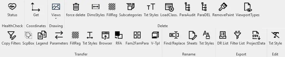
pyRevit is a free, open-source Python framework that bolts hundreds of automation, QA, and data-mining commands onto Autodesk Revit. Think Dynamo speed–but–with–Python, wrapped in a tidy ribbon tab.
Why you need it here
Several features in the PD template—the Model-Health Gauge, the one-click QA schedules launcher, and assorted right-click utilities—light up only when the PDtool pyRevit extension is present.
| Step | Action |
|---|---|
| 1 | Visit https://pyrevitlabs.notion.site and grab the pyRevit installer (template tested on v 5.1.0). |
| 2 | Run the installer – it adds a “pyRevit” tab to Revit and a little gear-wheel in the Windows tray. |
| 3 | Log in to https://projectdesign.io/account/downloads/ and download PDtool.extension.zip. |
| 4 | Make a home for extensions – e.g. C:\pyRevit – and unzip the file so you end up with: C:\pyRevit\PDtool.extension\ |
| 5 | Launch (or restart) Revit – pyRevit performs an auto-scan and the new pyRevit tab appears. |
| 6 | go to pyRevit TAB >pyRevit>Settings >Add Folder> Add Paf to your pyRevit folder (as on screenshot) > Reload pyRevit |
| 7 | Open a model based on this template; the Model-Health Gauge should animate and the PD ribbon will list the QA and productivity tools. |
Follow these six steps
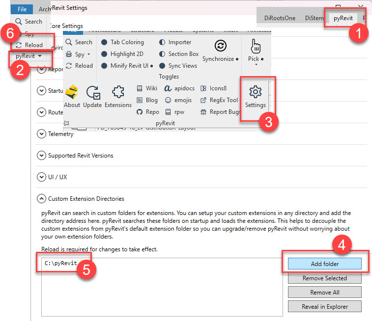
That’s it—automation unlocked, no code required.
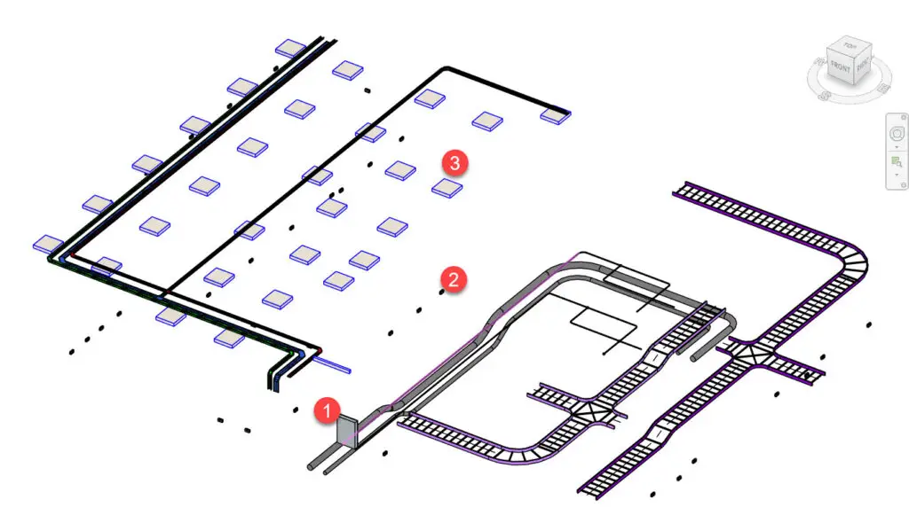
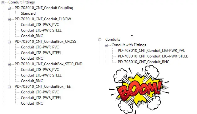
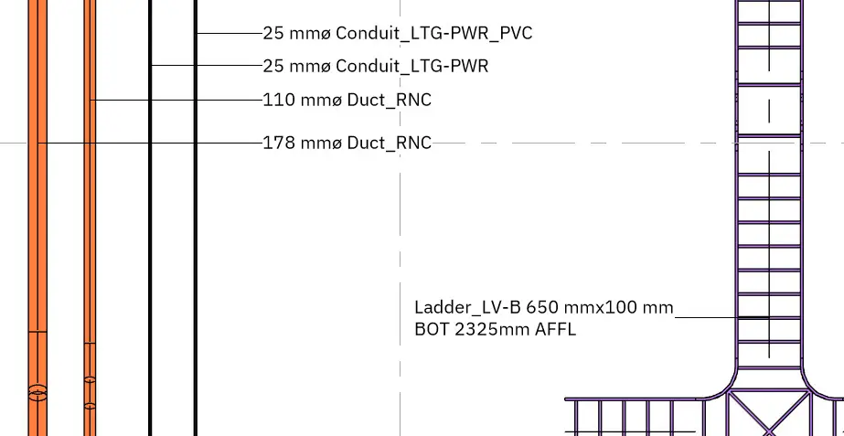
Three conduit systems in the template, LTG-PWR (steel), LTG-PWR (PVC),and Rigid Non-metallic Conduit RNC twin-wall PVC, have been pre-set so that:
| System | Family/type prefix | Size catalogue (mm OD) | Bend radius table follows “long” & “min” |
|---|---|---|---|
| Steel conduit (lighting & power) | PD-703010_CNT_Conduit_LTG-PWR_steel | 20 – 63 | PD_Conduit_Elbow_Metric_Steel_v25.1.1.csv |
| Steel conduit (lighting & power) | PD-703010_CNT_Conduit_LTG-PWR_pvc | 20 – 63 | PD_Conduit_Elbow_Metric_PVC_v25.1.1.csv |
| Twin-wall PVC RNC | PD-703010_CNT_Conduit_RNC | 20 – 178 | PD_Conduit_Elbow_Metric_RNC_v25.1.1 |
Each system ships with a full set of fittings already mapped to the relevant lookup table and placed in the two view templates PD_703010-10_Containment_(working) and …(published). No type-creation required – just model.
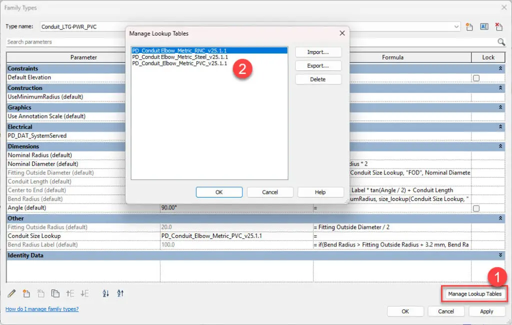
Bend Radius =
IF(UseMinimumRadius,size_lookup(Conduit Size Lookup, “BRad_Min”, 2.5 * OutsideDiameter, OutsideDiameter),size_lookup(Conduit Size Lookup, “BRad_Long”, 2.5 * OutsideDiameter, OutsideDiameter))
Conduit Size Lookup points to the embedded table (PD_Conduit Elbow – Steel, …PVC, …RNC).
For the tweakers among us, the three CSV files that drive those elbows are included in the template bundle:
They’re already embedded in the elbow family, so the system works out-of-the-box; the loose files are there purely for curiosity, audit, or future expansion (add a new size, re-import, job done).
If you don’t plan on editing bend data, feel free to ignore them—and definitely don’t delete the embedded copy, or Revit will fall back to the 2.5 × OD safety net, and your sweeps will look suspiciously tight.
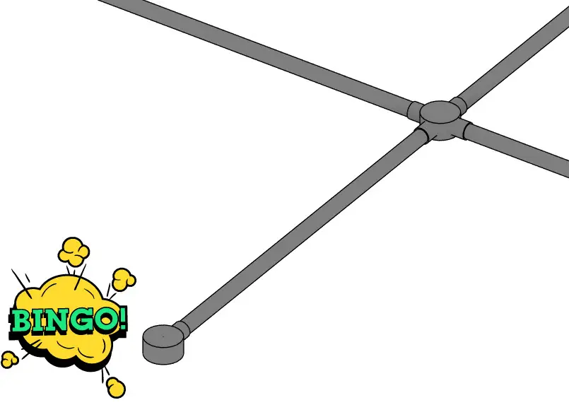
A single “Standard Conduit Coupling” family is assigned to every conduit type. Its only real job is to keep Revit’s Slice tool happy; we’re not interested in counting couplers, only total conduit length. In other words, modelling three-metre conduit lengths is pointless, so let’s leave the auto-couplers in place for slicing, but don’t waste time manually adding them.
The template includes a standard UK Stop-End conduit box for finishing dead-end runs. Revit will not drop this fitting automatically, so add it manually when a conduit terminates.
Systems ▶ Conduit Fitting ▶ PD-703010_CNT_ConduitBox_STOP_END.
Place only where the run genuinely stops.
Below is an inventory of the content you just gained. Keep it handy; if it’s not on this list, you probably don’t need it.
All snap automatically onto tray, ladder, or conduit runs.
| Family Name | Use |
|---|---|
| PD-703010_CNT_Conduit Coupling | Auto-inserted by Slice; maintains run continuity |
| PD-703010_CNT_ConduitBox_CROSS / _TEE / _STOP_END | UK conduit boxes for cross-overs, tees, dead-ends |
| PD-703010_CNT_Conduit_ELBOW | Elbow that reads the steel/PVC/RNC lookup tables |
| Family Name | Use |
|---|---|
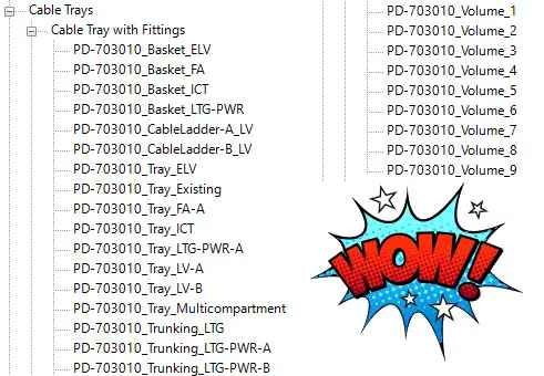
| PD_703010_Fitting_Horizontal Bend / Cross / Tee | Standard tray bends & junctions |
| PD_703010_Fitting_Vertical Inside Bend / Outside Bend | Vertical sweeps for tray runs |
| PD_703010_Fitting_Reducer / Union | Width transitions & joiners |
| PD_703010_Fitting_Ladder … (same set as above) | Ladder versions, plus Vertical Inside/Outside bends |
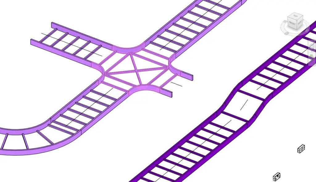
No hand-rotating, no “pick family” pop-ups—draw, and let Revit drop the right node.
| Symbol | Description |
|---|---|
| PD_ANS_SH_MCC | Motor-control centre |
| PD_ANS_SH_Switchboard | Main LV switchboard |
| PD_ANS_SH_Main_Earth_Terminal & …_Risers | MET symbols |
| PD_ANS_SH_Meter | kWh / sub-meter |
| PD_ANS_SH_Protective Device (vertical & horizontal) | Fuse/MCB/RCBO block |
| PD_ANS_SH_Switch Disconnector | Isolator symbol |
| PD_ANS_SH_ATS | Automatic Transfer Switch |
| PD_ANS_SH_GEN_Symbol | Standby generator |
| PD_ANS_SH_Cable_ID | Bubble for cable tag |
| PD_ANS_SH_Distribution_Box | Sub-DB bubble |
| PD_ANS_SH_EPO | Emergency-power off |
| PV suite: _PV_Array / _PV_Inverter / _PV_Isolator | Complete PV feed-in set |
All symbols use the template text style (IBM Plex Sans 2.5 mm) and respect view scale.
Every tag below is already loaded and colour-matched to the text-style palette.
| Tag Family | Drops On | Key Parameters Shown |
|---|---|---|
| PD_TAG-Room | Rooms | Name, number |
| PD_TAG_Space / _Zone / _Area | Spaces / Zones | Name, number, conditioning |
| PD_TAG_Wall / _Door / _Ceiling / _Floor-Ffl-Ssl | Architectural | Type & mark data |
| Containment Tags | ||
| PD_TAG_CableTray-Size | Tray/Ladder | Width × height |
| PD_TAG_CableTray-Size-SystemServed | Tray/Ladder | Size + service |
| PD_TAG_CableTray-Size-SystemServed-InvertLevel | Tray/Ladder | Size + service + invert level |
| PD_TAG_CableTrayFitting-Size | Tray/Ladder fittings | Size |
| PD_TAG_Conduit-Size | Conduits | OD/ND |
| Electrical Equipment & Devices | ||
| PD_TAG_ElectricalEquipment_PanelName | Boards | Panel name, kVA |
| PD_TAG_LightingFixture_Type | Luminaires | Type mark, emergency flag |
| PD_TAG_FireAlarmDevice | FA devices | Address / type |
| PD_TAG_Wire_1.8 mm_CircuitReference | ||
| PD_TAG_Wire_2.5 mm_CircuitReference | Wires | Circuit ref in chosen text height |
| PD_TAG_Keynote / _Revision / _MC-FamilyDetails / _MechanicalEquipment_Type / _JoineryUnit | Misc. | Self-explanatory |
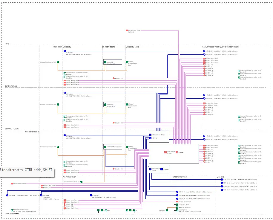
| View Name | What it shows |
|---|---|
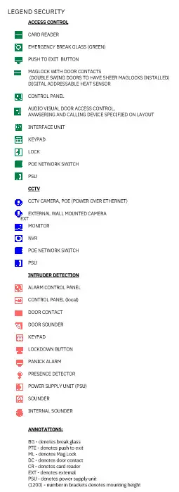
| Security Schematic | CCTV, ACS, intruder loops with PD_ANS_SH_ symbols |
| Typical Desk Layout Detail | Power, data, USB-C & AV outlets + clearance dims |
Both live on Sheet 00010—duplicate for new projects.
All symbols use the template text style (IBM Plex Sans 2.5 mm) and respect view scale.
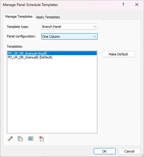
| Template Name | Column Layout | Typical Use |
|---|---|---|
| PD_UK_DB_(manual + load) | One bank, With calc columns (Ib, In, kVA, demand-factor) | Design WIP to check load an dcircuit lenght |
| PD_UK_DB_(manual) (Default) | One bank, No load columns | Used for Publication |
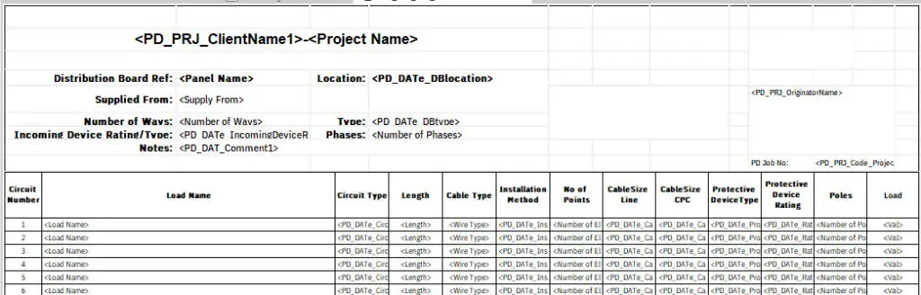
Select the board, or hit Edit Panel Schedule Template, pick the flavour you need – job done.
| Sheet ID | Size | Contents |
|---|---|---|
| PD_Legend Containment | A1&A0 | Trays, ladders, RNC colours, symbol key |
| PD_Legend Fire Alarm | A1&A0 | Device icons, loop labelling, cable types |
| PD_Legend Lighting | A1&A0 | Luminaire symbols, emergency icons, switching diagram |
| PD_Small-Power | A1&A0 | Device icons, labelling, |
| PD_Nurse-Call | A1&A0 | Device icons, labelling, |
| PD_Security | A1&A0 | Device icons, labelling, |
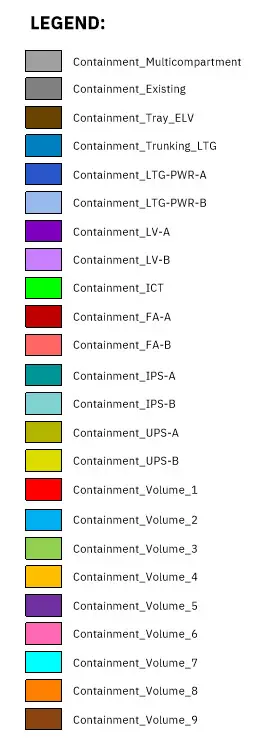
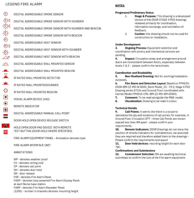

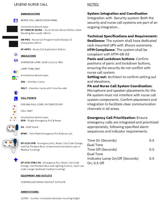
Feel free to copy-paste these legends to new sheets; the symbols stay live to the families.
| Sheet No. | View(s) | Purpose |
|---|---|---|
| E-10111 | Lighting plan L00, legend, notes | Shows how titles, revisions, keyplans link up |
| E-10211 | Small Power Layout | As above |
| E-10311 | Containment Layout | Combines legend, notes, and containment filter |
| DB1 | DB1 Circuit schedule | Demonstrates a panel schedule on sheet |
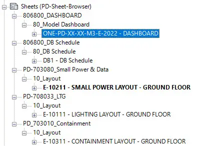
Swap the model views for your own and the title block.
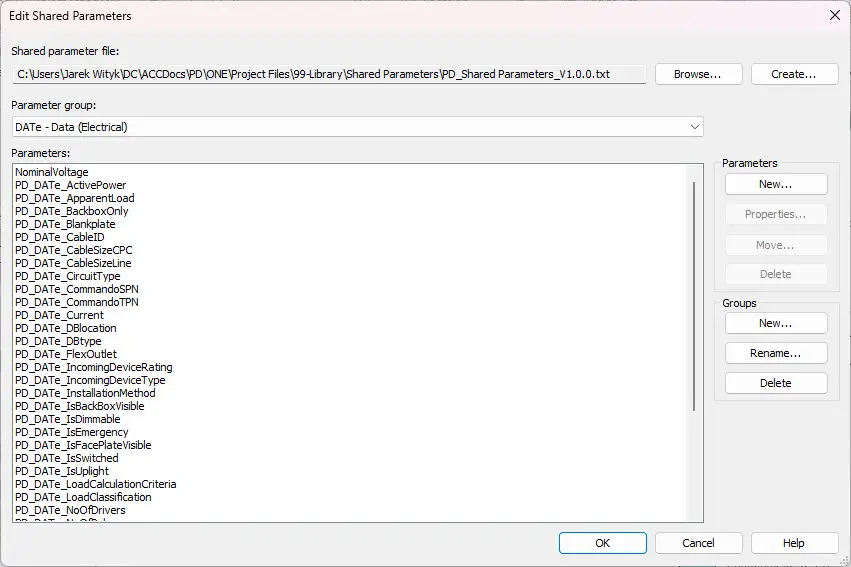
All custom parameters listed in PD_Shared Parameters_V1.0.0.csv are already loaded:
You shouldn’t have to add a single extra parameter for a standard UK electrical job—but if you do, keep the naming convention (camelCase for one-offs, group under Electrical – Power).
CamelCase means capitalising each “word” in a compound name, with no spaces or underscores.
Like so: ProjectNameSubElementOption1.
It’s called CamelCase because the capital letters form “humps” (someone was feeling poetic in a CS lab).
CamelCase is used for single-entity identifiers where readability and compactness are priorities. It eliminates the need for delimiters in straightforward compound names, making it ideal for parameters, variable names, and succinct file identifiers. For complex hierarchical naming, underscores _ and brackets () or [] are used to maintain clarity and structure.”
| Scenario | CamelCase is a Good Fit | Why |
|---|---|---|
| Short compound names | ProjectName, ViewFilter, SheetNumber | Easy to read, avoids visual clutter. |
| Internal identifiers / Parameters | FireRatingValue,ExportToIFC, RevitFamilyType | Common in software, scripting, coding standards. |
| When delimiters are unnecessary | NorthWingLayout instead of North_Wing_Layout | When the hierarchy is obvious from context. |
| File names in controlled systems | ClientDeliverableList2025 | Clean for systems that don’t like special characters. |
| Bad Fit | Why |
|---|---|
| When you want clear separation of blocks | Use _ or - instead for multi-layered structures. |
| For optional info or annotations | Use (Option1) or [Tag] for clarity. |
| In public file shares or client deliverables | Sometimes underscores are clearer for mixed audiences. |
CamelCase is great for naming single “things” — entities, variables, types.
But when you’re defining relationships between “things,” use delimiters.
ClientProject_LayoutType_(Option1)
This naming strategy works beautifully in BIM, CAD, and structured file naming.
In this Revit template, treat round parentheses (…) as human-friendly comments e.g., (Emergency) and square brackets […] as machine-readable tags that pin down hard attributes e.g., [IP65].
| Symbol | Used For | Tone | Example |
|---|---|---|---|
| (…) | Optional info, human-readable notes | Soft, explanatory | LuminaireSchedule_(Preliminary) |
| […] | Defining attributes, technical tags | Formal, machine-readable | FireAlarmPanel_[IP65] |
| Scenario | Use | Why |
|---|---|---|
| Adding optional, descriptive notes for humans | Round Parentheses (…) | They signal context but not structure |
| Defining a precise category, spec, or hard attribute | Square Brackets […] | They imply a structured, technical modifier |
| Status flags, revisions, phases (informational) | Round Parentheses (…) | Readable, non-intrusive |
| Configuration values, dimensions, controlled tags | Square Brackets […] | Machine-friendly, structured data feel |
Round brackets are your side comments — they’re for people.
Square brackets are your database columns — they’re for systems.
| Element | Naming Format | Example | Purpose |
|---|---|---|---|
| Core Identifiers | camelCase | cableSchedule, smallPowerLayout | Compact, structured |
| Contextual Info | (Round Brackets) | lightingLayout_(Emergency) | Optional, human-readable |
| Attributes / Filters | [Square Brackets] (if used) | ProtectedCorridor[FR120] | Structured tag, for filtered schedules |
| Drawing Annotations | Short, factual technical phrases | Connect lighting circuit to DB-01 | Clear installation instruction |
“camelCase is how we name systems. Brackets are how we tell humans which bit we’re talking about. And text annotations? Those are not for storytelling — they’re for telling exactly what needs to happen – make it idiotproof!”
Slash / and back-slash \ are reserved path separators in every modern operating system. The moment you slip one into a file name, two bad things happen:
Our naming strategy is meant to be WYSIWYG[1] across drawings, reports, schedules and file names.
Rule: Never use / or \ in any identifier, view, sheet, or exported file name.
Electrical circuits need to show the “path” from the board to the circuit. We keep that inside Revit parameters only, never in file names.
| Context | Allowed Form |
|---|---|
| Circuit parameter/tag | DB-01/1L1 |
| Any file name, view name, sheet name | DB-01_1L1 |
The underscore _ keeps the board ID glued to the circuit ID without upsetting Windows, macOS, SharePoint, or your friendly BIM coordinator.
| Character | Status | Example | Notes |
|---|---|---|---|
| _ underscore | Primary delimiter | DB-01_1L1_layout | Always safe. |
| () round brackets | Optional info | lightingLayout_(Emergency) | Human-readable. |
| [] square brackets | Structured tags | ProtectedCorridor[FR120] | Use sparingly. |
| / slash | Forbidden in names | DB/01_schedule | Only inside circuit parameters. |
| \ back-slash | Absolutely forbidden | DB\01\schedule | Same reason. |
“Slashes are path separators, not punctuation. Use them in a circuit tag if you must, but never in anything that needs saving, syncing, or emailing. Underscores cost nothing and save hours of forensic file-hunting.”
[1] WYSWIG – what you see is what you get
This section explains the six-digit headers that appear at the start of every
These headers let anyone sort or isolate content by system in a single click, while still mapping back to full Uniclass codes for data exchange.
| Item | Full Uniclass token | Project header | Rationale |
|---|---|---|---|
| Prefix | Ss_ | (removed) | Keeps the code numeric so it sorts naturally in both Revit and Windows Explorer. |
| Delimiters | _ (underscores) | (removed) | Removed to simplify. |
| Content | first three numeric pairs | kept | Retains the hierarchy: Group → Sub-group → Section (e.g. 70 80 33). |
| Children | fourth pair | kept only when needed | Used if two sub-systems would otherwise collide (e.g. Lightning = 70302545). |
Net result: the Uniclass string Ss_70_80_33 becomes the lean, human-friendly header 708033.
We remove nothing that affects traceability; the stripped code still back-maps one-to-one to Uniclass.
| Header | Description | Full Uniclass source |
|---|---|---|
| 354000 | Architectural setting-out (gridlines, control points, datums, levels) | Zz_35_40 Gridlines (CAD table) |
| 757054 | Lighting control & monitoring | Ss 75 70 54 10 |
| 708033 | Lighting (general & emergency) | Ss 70 80 33 |
| 703045 | LV distribution (mains, risers, switchgear) | Ss 70 30 45 45 |
| 703080 | Small power and data outlets | Ss 70 30 80 (merged per BEP note) |
| 751021 | Structured cabling – copper & fibre | Ss 75 10 21 |
| 751070 | Audio-visual/public AV systems | Ss 75 10 70 |
| 703010 | Cable containment (tray, ladder, basket) | Ss 70 30 10 |
| 755028 | Fire & smoke detection & alarm | Ss 75 50 28 |
| 754000 | Security (access, CCTV, intruder) – parent bucket | Ss 75 40 |
| 755011 | Nurse call & medical location systems | Ss 75 50 11 57 |
| 703025 | Earthing, bonding & lightning protection | Ss 70 30 25 (children 25/45) |
| 256030 | BWIC – service penetrations & fire-stopping | Ss 25 60 30 (building fabric) |
| 404015 | Combined services - coordination drawings | PM 40 40 15 (Project-Mgmt table) |
| 806800 | PD Standard reserved code! 80=P in ASCII, 68=D in ASCII, 00=NUL | n/a |
[1] Reference: https://uniclass.thenbs.com/
| PDcode | [5] | SystemClassification | [6] | view series [7] | [5] | Description[8] | [5] | Optional Information in Parentheses () | [5] | version |
|---|---|---|---|---|---|---|---|---|---|---|
| PD | _ | XXXXXX | – | XX | _ | XX | _ | XX | _ | xX |
[5] Delimiter Underscore (U+0332).
[6] Delimiter Hyphen-Minus (U+002D).
[7] See section 2.9.1 Series prefix XX to distinguish layout from sections while maintaining consistency
[8] Use camelCase or hyphens to separate words in View-Description
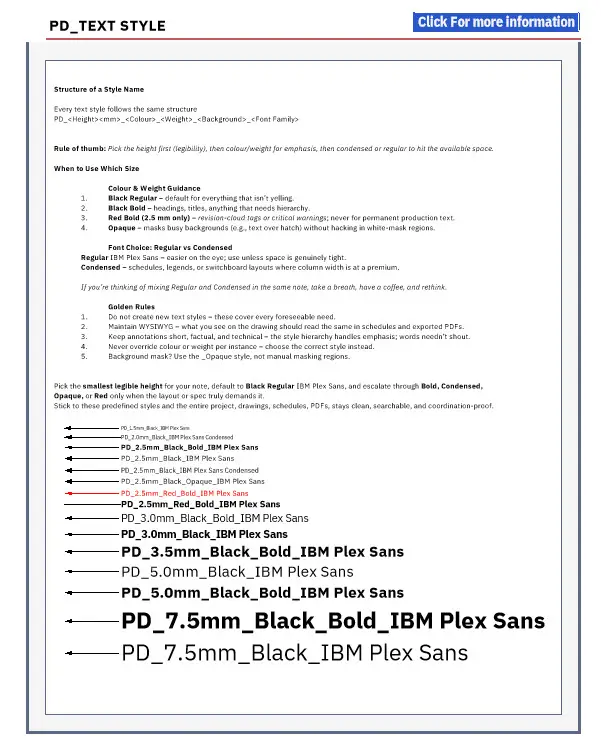
Every text style follows the same structure
PD_<Height><mm>_<Colour>_<Weight>_<Background>_<Font Family>
| Token | Meaning | Example |
|---|---|---|
| PD | Template prefix – identifies it as ours | PD_… |
| Height | Printed text height in millimetres | 2.5mm |
| Colour | Output colour (Black or Red) | …_Black_… |
| Weight | Bold or omitted (regular) | …_Bold_… |
| Opaque | Background mask on | …_Opaque_… |
| Font Family | IBM Plex Sans flavour | IBM Plex Sans Condensed |
Rule of thumb: Pick the height first (legibility), then colour/weight for emphasis, then condensed or regular to hit the available space.
| Size | Typical Use | Styles Available |
|---|---|---|
| 1.5mm | Tightest dims, leader notes inside symbols | PD_1.5MM_Black |
| 2.0mm | Schedules, tagging in crowded views | PD_2.0mm_Black_Condensed |
| 2.5mm | General notes, keynotes, circuit IDs | Regular / Bold / Condensed / Red Bold / Opaque |
| 3.0mm | Equipment labels, panel titles, sub-headings | Regular / Bold |
| 3.5mm | View titles, section heads | Bold only |
| 5.0mm | Sheet titles, major drawing headings | Regular / Bold |
| 7.5mm | Cover sheet project titles, big disclaimers | Regular / Bold |
If you’re thinking of mixing Regular and Condensed in the same note, take a breath, have a coffee, and rethink.
Pick the smallest legible height for your note, default to Black Regular IBM Plex Sans, and escalate through Bold, Condensed, Opaque, or Red only when the layout or spec truly demands it.
Stick to these predefined styles and the entire project, drawings, schedules, PDFs, stays clean, searchable, and coordination-proof.
Dimension Styles in a Nutshell.
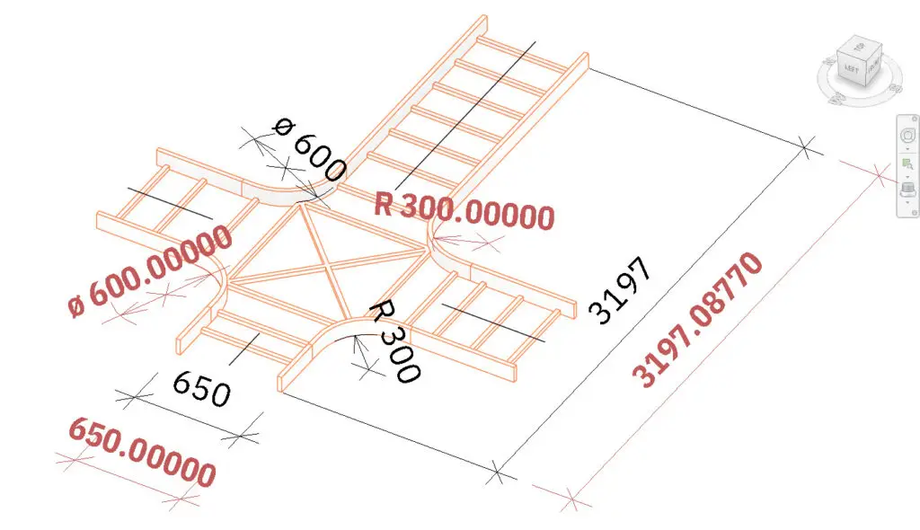
All dimension types [linear, radial, diameter, angular, even arc-length] use a single 2.5 mm text height and the same naming syntax: PD_DIM_2.5MM_<TYPE>_<STD/ACC>_<Font>
Pick the STD version for anything that will be published (project rounding, black text) and flip to the ACC version when you need forensic accuracy checks (five decimal places, red & bold IBM Plex Sans Condensed).
Never override units by hand; never invent new styles. Draw with STD, audit with ACC, hide or delete the red numbers before publishing.
In short: “STD to publish, ACC to interrogate – if you can count five decimals, you’re still in draft.”
We keep dimension styles lean-and-mean: one text height, two accuracy levels, four geometry types.
If you can’t find the right style in this list, you’re either measuring the wrong thing or inventing work for yourself.
| Style Name | Dimension Family | Purpose | Units & Rounding | Font |
|---|---|---|---|---|
| PD_DIM_2.5MM_LINEAR_STD_IBM Plex Sans | Linear / Arc length | Published lengths & offsets | Project default | IBM Plex Sans |
| PD_DIM_2.5MM_RADIUS_STD_IBM Plex Sans | Radial | Published radii & bends | Project default | IBM Plex Sans |
| PD_DIM_2.5MM_DIAMETER_STD_IBM Plex Sans | Diameter | Published diameters (luminaires, ducts) | Project default | IBM Plex Sans |
| PD_DIM_2.5MM_ANGLE_STD_IBM Plex Sans Condensed | Angular | Published angles (bracket swings, beam spreads) | Project default | IBM Plex Sans Condensed |
| PD_DIM_2.5MM_LINEAR_ACC_IBM Plex Sans Condensed | Linear / Arc length | Accuracy check — clash tolerances | 5 dp | Condensed |
| PD_DIM_2.5MM_RADIUS_ACC_IBM Plex Sans Condensed | Radial | Accuracy check — tight radii audits | 5 dp | Condensed |
| PD_DIM_2.5MM_DIAMETER_ACC_IBM Plex Sans Condensed | Diameter | Accuracy check — critical bores | 5 dp | Condensed |
| PD_DIM_2.5MM_ANGLE_ACC_IBM Plex Sans Condensed | Angular | Accuracy check — fractional-degree checks | 5 dp | Condensed |
Why the “Condensed” font for ACC styles?
Five-decimal strings are long; Condensed keeps them from trampling your symbols.
PD_DIM_2.5MM_<TYPE>_<STD/ACC>_<FontFamily>
One button-swap; zero nasty surprises on site.
Cheat Sheet:
“STD to publish, ACC to interrogate. If a number shows five decimals in red, you’re still in the draft.”
The Canonical Snippet
If you ask most designers for “the placeholder text,” they’ll give you the first sentence of that Latin mash-up:
“Lorem ipsum dolor sit amet, consectetur adipiscing elit, sed do eiusmod tempor incididunt ut labore et dolore magna aliqua.”
(If you’re curious, a loose English rendering starts “Pain itself is very important to us…” — oddly poetic for Distribution board Lipsum Hub Blog.)
All information in the PD Revit Template follows PROJECT DESIGN (IO) standards which have been described in detail in our DOCUMENT NAMING STRATEGY.
| Project No | [1] | Originator | [1] | Functional Breakdown | [1] | Spatial Breakdown | [1] | Form | [1] | Discipline | [1] | Number | [2] | Title / Description |
|---|---|---|---|---|---|---|---|---|---|---|---|---|---|---|
| XXXX(XX) | - | XX(X) | - | XX | - | XX | - | X(X) | - | X | - | XXYYY | _ | Drawing |
Please follow the link for more details: DOCUMENT NAMING STRATEGY.

“The inner radius of a conduit bend should be not less than 2.5 times the outside diameter of the conduit.” On-Site Guide 18th A2, Comment under Table E3