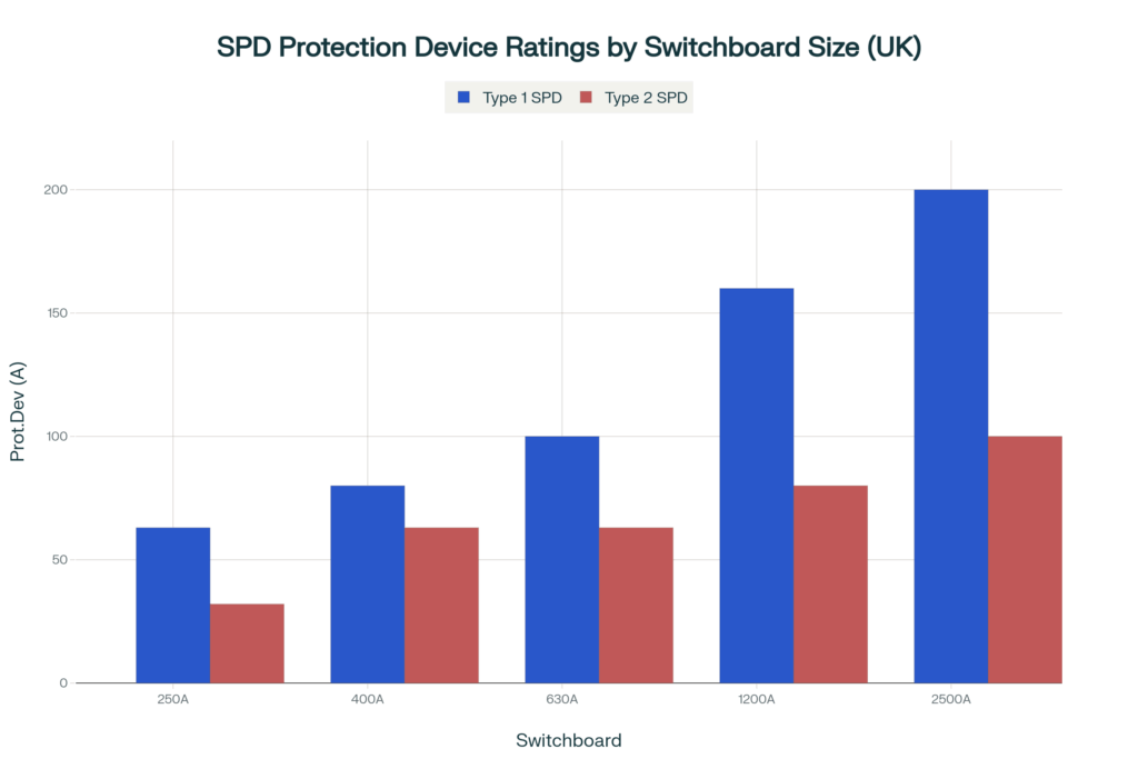
Based on extensive research of UK standards, manufacturer specifications, and industry practices, here are practical “rule of thumb” protection device ratings for Type 1, Type 2 and Type 1+2 surge protection devices (SPDs) in main switchboards.
Type 1 and Type 1+2 combined SPDs at service entrance installations, backup protection ratings typically range from 63A to 250A depending on switchboard size and Lightning Protection Level (LPL), representing approximately 15-25% of the switchboard rating[1] [2]. For Type 2 SPDs, protection ratings are generally lower, ranging from 32A to 100A[1] [3].
| Switchboard Rating | LPL I/II Backup Protection | LPL III/IV Backup Protection | Alternative gG Fuse | Short-Circuit Capacity |
|---|---|---|---|---|
| 250A | 80A B/C curve MCCB | 63A B/C curve MCCB | 63A gG / 80A gG | 10-25kA |
| 400A | 100A B/C curve MCCB | 80A B/C curve MCCB | 80A gG / 100A gG | 10-25kA |
| 630A | 125A B/C curve MCCB | 100A B/C curve MCCB | 100A gG / 125A gG | 15-36kA |
| 800A | 160A B/C curve MCCB | 125A B/C curve MCCB | 125A gG / 160A gG | 15-36kA |
| 1000A | 200A B/C curve MCCB | 160A B/C curve MCCB | 160A gG / 200A gG | 25-36kA |
| 1200A | 200A B/C curve MCCB | 160A B/C curve MCCB | 160A gG / 200A gG | 25-36kA |
| 1600A | 250A B/C curve MCCB | 200A B/C curve MCCB | 200A gG / 250A gG | 25-50kA |
| 2000A | 315A B/C curve MCCB | 250A B/C curve MCCB | 250A gG / 315A gG | 25-50kA |
| 2500A | 400A B/C curve MCCB | 315A B/C curve MCCB | 315A gG / 400A gG | 25-50kA |
| 3200A | 500A B/C curve MCCB | 400A B/C curve MCCB | 400A gG / 500A gG | 50-100kA |
BS 7671 Compliance: Every SPD must have its own coordinated overcurrent protective device per Regulation 534.4.1.5 [4] [5]. The main fuse or switch-fuse alone is not sufficient protection.
Coordination Requirements: The protective device must withstand 15 successive impulse currents at the SPD’s nominal discharge current (In) without tripping, while providing effective protection against short circuits and overload conditions [1] [2].
MCCB Characteristics: Type B or C curve thermal-magnetic MCCBs are preferred for coordination. Type B curve (3-5×In magnetic trip) provides better coordination for most applications [6] [7].
| Switchboard Rating | Recommended Protection Rating | Device Type | Alternative gG Fuse | Short-Circuit Capacity |
|---|---|---|---|---|
| 250A | 32A | MCB/MCCB B/C | 32A gG | 6-10kA |
| 400A | 50A | MCB/MCCB B/C | 50A gG | 6-10kA |
| 630A | 63A | MCCB B/C | 63A gG | 10-15kA |
| 800A | 80A | MCCB B/C | 80A gG | 10-15kA |
| 1000A | 100A | MCCB B/C | 100A gG | 15-25kA |
| 1200A | 100A | MCCB B/C | 100A gG | 15-25kA |
| 1600A | 125A | MCCB B/C | 125A gG | 25-36kA |
| 2000A | 160A | MCCB B/C | 160A gG | 25-36kA |
| 2500A | 200A | MCCB B/C | 200A gG | 25-50kA |
| 3200A | 250A | MCCB B/C | 250A gG | 50-100kA |
Domestic Applications: For single-phase consumer units, 32A MCB Type B is most common [9] [3]. Many manufacturers supply Type 2 SPDs with integrated 32A MCBs for convenience.
Commercial Applications: Three-phase Type 2 SPDs typically use 63A protection for most commercial installations [8] [10].
TN-C-S Earthing: Most UK installations use TN-C-S earthing systems, which affect SPD connection configuration. SPDs should be connected in “3+0” or “4+0” mode for optimal protection [11].
| Lightning Protection Level | Maximum Lightning Current (10/350 μs) | Protection Effectiveness | Required SPD Capacity (per pole) |
|---|---|---|---|
| LPL I | 200 kA | 98% | 25 kA |
| LPL II | 150 kA | 95% | 18.75 kA |
| LPL III | 100 kA | 88% | 12.5 kA |
| LPL IV | 100 kA | 81% | 12.5 kA |
LPL selection requires professional risk assessment per BS EN 62305-2 [*]. Key factors include:
Building Type and Occupancy: Critical facilities require LPL I/II protection (98-95% effectiveness), while standard commercial and residential applications typically use LPL III/IV (88-81% effectiveness) [*].
Geographic Location: Areas with high lightning density (>2 strikes/km²/year) typically require higher protection levels [*].
Consequence of Failure: Life safety considerations, economic impact, and service continuity requirements influence LPL selection[*].
Structural Lightning Protection: Buildings with external lightning protection systems require Type 1 or Type 1+2 SPDs coordinated with the LPS [*].
Type 1+2 combined devices are preferred for [*]:
Service entrance installations with limited space
Buildings with external lightning protection systems
Installations fed by overhead power lines
Critical facilities requiring extra protection
The protective device’s breaking capacity must equal or exceed the prospective short circuit current at the installation point[1] [2]. This typically requires:
10-25kA rating for most commercial applications
25-50kA rating for large industrial installations with high fault levels
Per BS 7671 Section 534.4.8, SPD connecting conductors must be [13]:
Minimum 4mm² copper if line conductors ≥4mm²
Minimum 16mm² copper for Type 1 SPDs where structural lightning protection is installed
Keep connections as short as possible to minimize inductive voltage drop
Required Protection: 80A Type B MCCB
SPD Rating: 50kA (8/20 μs) or 12.5kA (10/350 μs) per pole
Cable Sizing: 6mm² live/neutral, 16mm² earth
Connection Length: Maximum 1.0m total
Required Protection: 200A Type B MCCB
SPD Rating: 75kA (8/20 μs) or 18.75kA (10/350 μs) per pole
Cable Sizing: 16mm² live/neutral, 25mm² earth
Connection Length: Preferably ≤0.5m total
Required Protection: 32A Type B MCB
SPD Rating: 20kA (8/20 μs) or 12.5kA (10/350 μs)
Cable Sizing: 2.5mm² live/neutral, 6mm² earth
Connection Length: Maximum 1.0m total
SPD backup protection must consider selectivity (discrimination) with upstream protection devices to prevent loss of supply during SPD operation [*]. This requires selectivity studies considering:
Time-current characteristics
Energy let-through values
Selective tripping under fault conditions
Risk Assessment Required: These are general guidelines only. Proper risk assessment per BS EN 62305-2 may require different ratings based on specific exposure levels, equipment sensitivity, and consequence of failure [15].
No Substitute for Professional Design: These rules of thumb are for concept design only. Final SPD selection and coordination must be performed by qualified electrical engineers using manufacturer data and proper coordination studies [1].
Standards Evolution: SPD standards continue to evolve. BS EN IEC 61643-01:2025 introduced new requirements that may affect future coordination practices [16]. Always verify compliance with current standards.
Installation Quality Critical: Even properly rated SPDs will fail to provide adequate protection if installation quality is poor. Short, direct connections and proper earthing are essential for effective surge protection [13] [14].
These practical guidelines provide electrical engineers with reliable starting points for SPD protection device selection in UK TN-C-S installations, while emphasising the critical importance of manufacturer verification and professional engineering judgment in final design decisions.