
(Edition 2025 – aligned with BS 7671:2018+A2:2022, Amendment 3 (2024), and draft Amendment 4 (2026), also drawing from official UK Power Networks standards)
Applies to earthing, main protective bonding, supplementary bonding, and high-integrity protective conductors (HIPCs) for low voltage (<1 kV a.c.) electrical installations.
Mandatory requirements are directly referenced from BS 7671, with clause numbers provided.
Informative and best-practice guidance is referenced from:
IET Guidance Note 8 (Earthing & Bonding)
On-Site Guide (OSG)
Energy Networks Association (ENA) G12/3
Relevant DNO (Distribution Network Operator) policies (e.g., SPEN EART-01-002 for PNB)
Statutory requirements include:
Electricity at Work Regulations 1989
Electricity Safety, Quality & Continuity Regulations 2002 (ESQCR)
“A distributor shall, when providing a new connection at low voltage, make available his supply neutral conductor or, if appropriate, the protective conductor of his network for connection to the protective conductor of the consumer’s installation” – ESQCR Regulation 24(4)
Refer to the system identification flowcharts and records. Typical arrangements:
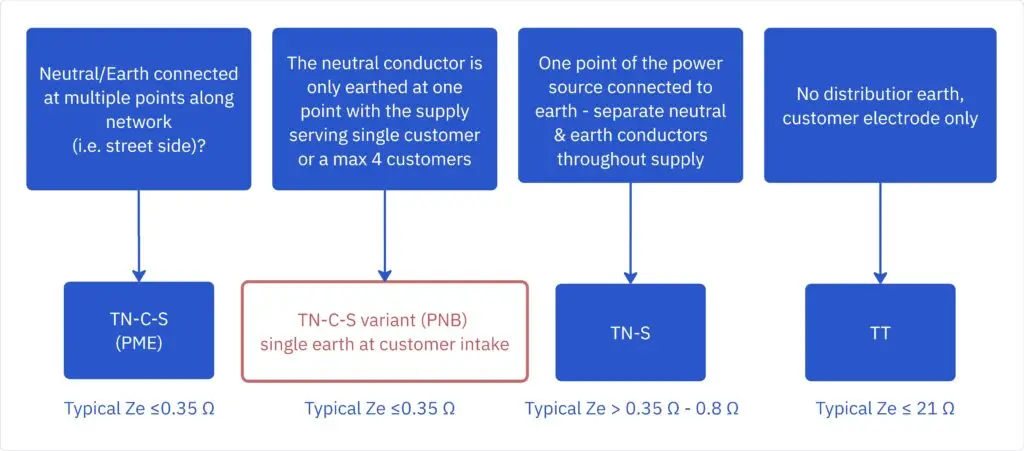
| Visual/Record Indicator | Likely System | Typical Ze | Notes |
|---|---|---|---|
| CNE cable & multiple distributor electrodes | TN-C-S (PME) | ≤ 0.35 Ω | Reg 411.4.1 + ENA G12/3, EDS 06-0016, Table B.4 |
| CNE cable & single electrode at intake | TN-C-S variant (PNB) | ≤ 0.35 Ω | Treated as TN-S inside; confirm with DNO. EDS 06-0016, Section 8 Date: 11/12/2024 Version:9.1 |
| Separate neutral & earth throughout supply | TN-S | 0.35–0.8 Ω | No PEN in building, EDS 06-0012, Table 4-2 |
| Customer electrode only, no distributor earth | TT | ≤ 21 Ω (with RCD) | BS 7671 Reg 411.5 |
| PEN not separated inside premises | TN-C | n/a | Not permitted indoors (BS 7671 Reg 312.2) |
Amendment 3:2024 recommends an additional earth electrode for all TN systems (Reg 411.4.2).
Although PME is the preferred option protective neutral bonding (PNB) may provide a better solution in circumstances where it is not practical to install the LV earth at the transformer. In a PNB earthing system the LV neutral conductor is connected to an earth electrode at a point remote from the transformer at or near the customer’s supply terminals […].
PNB may only be used if the following criteria are satisfied:
The purpose of protective earthing is to ensure that, in the event of a fault, such as between a line conductor and an exposed-conductive-part or circuit protective conductor, sufficient current flows to operate the protective device, i.e. fuse to blow, circuit-breaker to operate or RCD to operate, in the required time.
Every exposed-conductive-part (a conductive part of equipment that can be touched and which is not a live part but which may become live under fault conditions) shall
be connected by a protective conductor to the main earthing terminal and, hence, the means of earthing for the installation. [411.4.2, 411.5.1 BS7675]
Bond every incoming extraneous-conductive-part (e.g., water, gas, oil, structural steel, lightning down-conductors, metallic cable sheaths) to the Main Earthing Terminal (MET) “as near as practicable to the point of entry” (Reg 544.1.2).
For PME / PNB (per Table 54.8, BS 7671):
| PEN (Cu-equiv.) | ≤35 mm² | >35–50 mm² | >50–95 mm² | >95–150 mm² | >150 mm² |
|---|---|---|---|---|---|
| MPB (Cu) | 10 mm² | 16 mm² | 25 mm² | 35 mm² | 50 mm² |
For Non-PME (TN-S or TT):
Minimum: ½ earthing conductor CSA, at least 6 mm², maximum 25 mm² Cu (BS 7671 Reg 544.1.1).
Buried earthing conductor:
16 mm² Cu (protected)
25 mm² Cu (unprotected)
(Table 54.1)
Earth electrodes:
Resistance as low as practicable.
For TT: select electrode(s) to ensure Ra×IΔn≤50 V (BS 7671 Reg 411.5.3).
“…a conductive part liable to introduce a potential, generally Earth potential, and not forming part of the electrical installation.”
Definition (BS 7671 Part 2)
Step 1: Definition Application
Apply the complete BS 7671 definition – all three criteria must be met.
Step 2: Resistance Test (IET GN 8 Method)
Measure resistance between part and MET
R > 22 kΩ: May be treated as not extraneous
R ≤ 22 kΩ: Apply engineering judgement
Step 3: Documentation
BS 7671 Regulation 642.3: All decisions and test values must be recorded
R≤50 V/Ia between simultaneously accessible conductive parts.
| RCD IΔn | 30 mA | 100 mA | 300 mA |
|---|---|---|---|
| Max R | 1.67 kΩ | 500 Ω | 167 Ω |
Follow Regs 544.2.1–544.2.2 or OSG Table 4.6 (e.g., 2.5 mm² Cu with mechanical protection, 4 mm² otherwise).
Required where protective-conductor current >10 mA (e.g., harmonic filters, UPS, VSDs).
Ring final circuits with ring CPC inherently satisfy.
Acceptable alternatives:
Dual single-core CPCs
Multicore cable with split armour
Separate conduit
Label distribution boards:
“High-Integrity Protective Conductors – do not remove CPCs” (BS 7671 Reg 543.7.1.205).
| Device | Acceptable Use | Clause |
|---|---|---|
| Type AC | Fixed loads proven free of d.c. residuals | BS 7671 Reg 531.3.3 |
| Type A | General socket / lighting | Default |
| Type F | Heat pumps, induction hobs, EV charging | Manufacturer spec |
| Type B | PV inverters, VSDs, battery systems | Manufacturer spec, IEC 62423 requirements |
Amendment 3:2024 introduces new bidirectional RCBO/RCD symbols for devices supporting power flow from embedded generation.
Circuit Parameters:
230 V TN-S radial circuit
32 A Type B MCB
Zs = 0.15 Ω
Calculation Steps:
Step 1: Fault Current
Ief = Uo / Zs = 230 / 0.15 = 1,533 A
Step 2: Operating Time
t = 10 s (from manufacturer’s time/current curve)
Step 3: Energy Calculation
I²t = (1,533)² × 10 = 23,508,900 A²s
Step 4: Conductor Sizing
S = sqrt(I²t) / k
Where k = 143 (for 70°C PVC copper – BS 7671 Table 54.4)
S = sqrt(23,508,900) / 143 = 33.9 mm²
Step 5: Selection
Select next standard size: 35 mm² Cu
"A PME earth terminal shall not be provided to construction or demolition sites because it is not possible to verify that the installation continuously complies with the bonding requirements of BS 7671"
EDS 06-0017
Preferred earthing: TT or PNB.
PME is allowed only if all ECPs are reliably bonded (Reg 704.411.3.1).
RCDs:
500 mA time-delay for circuits >32 A
30 mA for circuits ≤32 A (Reg 704.411.3.2)
ENA G12/3 warns of neutral-current diversion risk on steel-framed PME sites—electrode system often mandated.
Permitted Earthing Systems:
TT with RCD protection (preferred)
TN-S from dedicated transformer
TN-S via isolating transformer
Electrode Separation Requirements:
Minimum 2m from PME electrodes
Minimum 8m from HOT substations
| Error | Why | Correct Approach |
|---|---|---|
| Main protective bonding conductors must be sized to BS 7671 Reg 544.1.1 | EDS 06-0016 LV Network Earthing Design (Version: 9.1, Date: 11/12/2024) Section 8 " A PNB earth terminal shall be considered a PME earth terminal" | Where PME conditions apply use Table 54.8 (not Table 54.7) |
| Taking 22 kΩ as a mandatory pass/fail | It is informative only | Always use BS 7671 definition; 22 kΩ is a screen |
| Undersizing bonding to outbuildings | Separate structures need own MPB | Bond to MET in that building, CSA ≥ CPC of supply SWA |
| Omitting extra electrode on TN-C-S | Now recommended (Amd 3) | Fit 2–4 m rod or plate; record Ra value |
| Leaving PEN combined inside a building | TN-C prohibited indoors | Separate PEN at intake (TN-C-S) or use TT |
Amendment 4 to BS 7671 introduces a new Section 545 specifically addressing functional earthing and functional-equipotential-bonding for Information and Communication Technology (ICT) equipment and systems [1] [2] [3]. This section represents a significant development as technology continues to evolve, particularly in renewable energy systems, data centers, and communication networks.
Main Functional Earthing Terminal (MFET): When multiple functional bonding conductors are present, a separate MFET must be installed for ease of connection [4]
Single Connection Rule: The MFET must be connected to the Main Earthing Terminal (MET) only once[4]
Combined Terminals: The MFET and MET may be combined where appropriate [4]
≤2 Ω to earth: This is the expected maximum resistance requirement for functional earthing systems [5] [6]
This low resistance value ensures effective operation of ICT equipment and proper electromagnetic compatibility (EMC) performance
Insulation Requirement: Functional bonding conductors must be insulated when not locally connected to the protective-equipotential-bonding system [4]
Separate Installation: Functional bonding conductors must be installed separately from protective conductors [4]
Prevention of Interference: This segregation prevents protective conductor currents from flowing along functional earthing conductors [7]
Pink Color Coding: Functional earth conductors must be identified using pink sleeving as per BS 7671:2018+A2 [8] [9] [10]
Alphanumeric Designation: Use “FE” for functional earth conductors [11]
Clear Marking: All functional earthing connections must be clearly labelled to distinguish from protective earthing [12]
Based on the draft requirements [4]:
2.5 mm² Cu (if mechanical protection is provided)
4 mm² Cu (if mechanical protection is not provided)
16 mm² Al (alternative material specification)
Section 545 applies to ICT systems including [3] [13]:
Broadcast equipment
Communication technology systems
Computer network systems
Data centers and telecommunications installations
Solar PV and battery storage systems
Power over Ethernet (PoE) applications
Electromagnetic Compatibility: Functional earthing is essential for maintaining signal integrity and reducing electromagnetic interference [14] [15]
High-Frequency Performance: Unlike protective earthing, functional earthing must handle high-frequency disturbances effectively [15]
Signal Reference: Provides a stable reference potential for sensitive electronic equipment [13]
Mesh Bonding Networks: ICT systems should use mesh-type bonding networks (MESH-BN) for optimal performance [13]
Multiple Interconnections: The functional earthing system should augment the main earthing system through multiple interconnections [13]
Proximity Requirements: Functional earthing should be located as close as possible to protected equipment [15]
Publication Date: Amendment 4 is expected to be published in 2026 [1] [2]
Implementation: All new installations will need to comply with Section 545 requirements once Amendment 4 becomes effective
Current Status: The requirements are currently in draft form and subject to revision based on public consultation feedback
UKPN EDS 06-0017 Customer LV Installation Earthing Design
UKPN EDS 06-0016 LV NETWORK EARTHING DESIGN (Version: 9.1, Date: 11/12/2024)
UKPN EDS 06-0016 LV NETWORK EARTHING DESIGN (some Images from Version: 4.0, Date: 12/04/2013)
BS7671: 2018 Amd 2 &3 Requirements for Electrical Installations
OnSite Guide
[1] NICEIC – Make a difference: have your say on Amendment 4:2026
[2] IET and BSI urges electrical industry to have its say on IET Wiring Regulations
[3] The impact of Amendment 4:2026
[4] IEC 60364-5-54 INTERNATIONAL STANDARD
[6] How to Determine Correct Number of Earthing Electrodes
[7] IET AMD 4 DPC – new section 545 – functional earthing
[8] Stay compliant: PVC Pink Sleeving for Functional Earth Conductors
[9] Fire industry regulatory update Pink sleeving must be used for functional earths
[10] Why must pink sleeving now be used for functional earths?
[11] IET Section 514 identification and notices in the Amendment No. 2 Draft for Public Comment
[13] Final draft ETSI EN 301 605 V1.1.1
[14] What is Functional Earth in Cables?
[15] Protective and Functional Grounding: Combined or Individual?


2 responses
In your ‘Conductor Sizing’ section you have PNB systems down as having their bonding conductors sized as per table 54.8 like a PME system, but in your ‘Common Errors’ section it’s written as PNB bonding conductors to be sized per table 54.7 like a TN-S system. There isn’t a great deal of guidance around this, though my understanding is that PNB systems can be sized per 54.7 like a TN-S system. Which is correct?
Thanks for picking that up, you’re right, my previous wording was inconsistent.(now updated – thanks to you)
In BS 7671, main protective bonding conductor sizing is per Reg 544.1.1. Table 54.7 is for CPC/protective conductor sizing, not main protective bonding. Where PME conditions apply, Reg 544.1.1 points you to Table 54.8 (sized to the supply PEN).
PNB isn’t explicitly defined in BS 7671, so the practical answer is how the DNO classifies the earth terminal. For example, UKPN state a PNB earth terminal is to be considered a PME earth terminal, so in that case bonding follows the PME/Table 54.8. If the terminal is not treated as PME, then you apply the non-PME part of 544.1.1 (min 6 mm², max 25 mm² Cu)