
ELI5-S2: BIM in Practice E6: Appointed Party context of information exchange Understanding the Appointed Party (T2-T4) Context of Information Exchange in BIM Welcome to the final instalment of our ELI5-S2
ELI5-S2: BIM in Practice E5: Lead Appointing Party context of information exchange Understanding the Lead Appointed Party (T1) Context of Information Exchange in BIM Welcome to the fifth installment of
ELI5-S2: BIM in Practice E4: Appointing Party context of information exchange Understanding the Appointing Party (T0) Context of Information Exchange in BIM Welcome to the fourth installment of our ELI5-S2
ELI5-S1:BIM Basics: E13_Understanding BIM Stages Understanding BIM Stages: Transitioning from BIM Levels to a Modern Framework In the world of Building Information Modeling (BIM), we often come across terms like

Understanding the Problem-Solving Process
Effective problem-solving is at the heart of success in any field. Drawing inspiration from the book “General Relativity for Babies” by Chris Ferrie, which simplifies complex topics into easy-to-understand concepts, I have created a straightforward guide to the problem-solving process.

Tip of the Day (TOD): How to Relinquish Locked Revit Models If you’ve ever been frustrated by locked Revit model elements when a team member is unavailable to relinquish them,
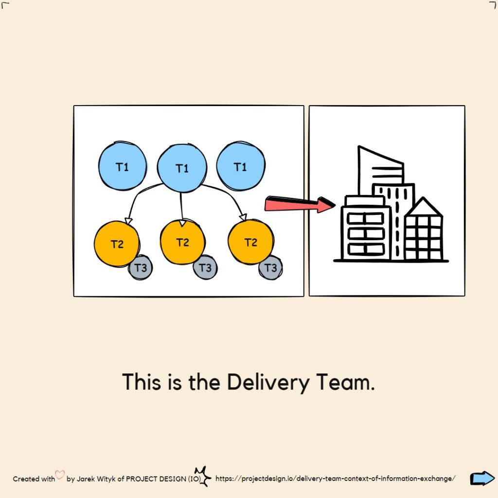
ELI5-S2 BIM in Practice E3 Delivery Team context of information exchange ELI5-S2: BIM in Practice E3: Delivery Team context of information exchange explained Understanding the context of information exchange from
ELI5-S2: BIM in Practice E2: Operational Team Context of Information Exchange Explained In any BIM project, understanding the context of information exchange during the operational phase is crucial. This post

ELI5-S2: BIM in Practice E1: Shared context of information exchange Introducing the “ELI5-S2 BIM in Practice” Series! Welcome to the first post in our new series, “BIM in Practice,” where
1. Generic Host in the Face-Based Family When you are in the face-based family, create void, and Cut the Generic Host This setup essentially simulates the cutting action within the

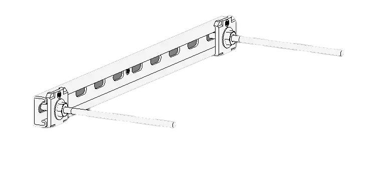
VEAM connectors refer to a specific type of electrical bayonet type connectors known for their robustness and reliability in harsh environmental conditions. These connectors are commonly used in various industries,
The transition from the BIM Levels to the concepts in the ISO 19650 series and the UK BIM Framework represents a shift in how we think about BIM maturity. However,
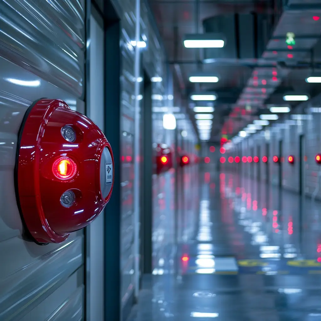
Guide to Visual Alarm Devices (VADs) in Fire Safety In high-noise workspaces or locations requiring hearing protection, Visual Alarm Devices (VADs) play a critical role in fire safety. They ensure

The term “Young Person” in the context of construction, Building Information Modeling (BIM), electrical engineering, or general engineering typically refers to a younger individual, often a recent graduate or entry-level

The term “X-ref” is commonly used as an abbreviation for “External Reference” in various technical and engineering fields, including construction, Building Information Modeling (BIM), and computer-aided design (CAD). Here’s a
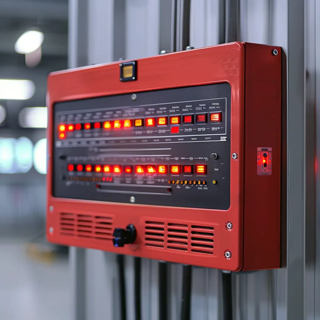
part of indicating equipment which visually indicates the zone of origin of a alarm of fire or faultwarning BS 4422 2005 Zone Indicator in Fire Alarm Systems The zone indicator

nozzle reactionforce acting in the opposite direction to the water stream leaving the nozzle BS 4422 2005 “Jet reaction,” also known as “nozzle reaction,” is a fundamental concept in fluid

extinguishing medium, usually water, leaving a nozzle as a continuous stream, water spray, or waterfog (mist) BS 4422 2005 Each of these methods has its own advantages and is chosen
Here is my list of reasons why so often we have incomplete Building Services Design before the project starts construction: Incomplete Building Services Design (BSD) before the commencement of construction

Mastering 3-Axis Rotation: Transform Revit Face-Based Families with Tiltable Geometry
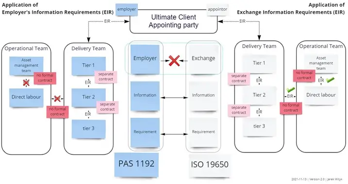
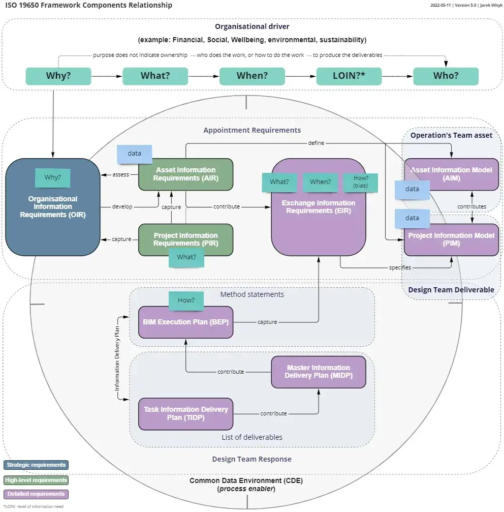
The Exchange Information Requirements (EIR) term introduced by BS EN 19650 replaces the PAS 1192 term Employer Information Requirements (EIR) on all projects where BS EN ISO 19650 compliance is

Summary
1. If the toilet has borrowed light and is less than 8m square:
a. There is no need for emergency lighting, however,
b. If there is a cubicle with full height door – therefore closed without borrowed lighting – then the EM lighting would be required in that cubicle.
2. If the overall toilet has no borrowed light,
a. And the WC cubicles do not have full-size doors; there should be at least one emergency outside row of cubicles.
b. If there is a cubicle with full height door – therefore closed without borrowed lighting – then the EM lighting would be required in that cubicle.
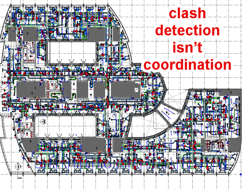
Coordination goes beyond orderly task execution, it transforms individual perspectives into shared, community-wide actions. It’s not just a subset of collaboration; it’s the engine that makes collaboration more than a patchwork of solo efforts.
That part of the earth fault loop impedance which is external to the circuit under consideration. For the supply cable it will be the impedance external to the installation. For
Z2 – That part of the earth fault loop impedance which comprises the impedance under earth fault conditions of the circuit protective conductor (cpc) of the circuit under consideration.
Z1 – That part of the earth fault loop impedance which comprises the impedance under earth fault conditions of the line conductor of the circuit under consideration.
An uninterruptible power supply (UPS) is used to maintain the supply to an essential service duringmains supply outages. On loss ofmains supply,a storage device in the UPS (battery) continues to
Uo Nominal line voltage to earth. Assumed to be 230 V for grid connected systems.
A system having one point of the source of energy directly earthed, the exposedconductive-parts of the installation being connected to earth electrodes electrically independent of the earth electrodes of the
A system having one or more points of the source of energy directly earthed, the exposedconductive-parts of the installation being connected to that point by protective conductors.