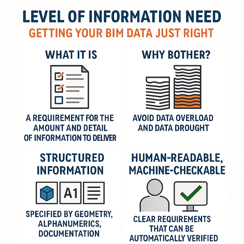
Ever feel like you’re drowning in BIM data you don’t need, or scrambling for details that should’ve been there? Enter the concept of Level of Information Need. It’s a straightforward idea buried behind a not-so-straightforward name (looking at you, BS EN ISO 7817-1:2024). In plain English, a Level of Information Need defines exactly what information should be delivered – no more, no less – for a given BIM use case or project stage.

Junction Box Requirements in Electrical Installations To ensure compliance with BS 7671:2018+A2:2022, the following requirements apply when using junction boxes in electrical installations: 1. Compliance with BS EN 60670-22 Any
ELI5-S1:BIM Basics: E13_Understanding BIM Stages Understanding BIM Stages: Transitioning from BIM Levels to a Modern Framework In the world of Building Information Modeling (BIM), we often come across terms like

VEAM connectors refer to a specific type of electrical bayonet type connectors known for their robustness and reliability in harsh environmental conditions. These connectors are commonly used in various industries,
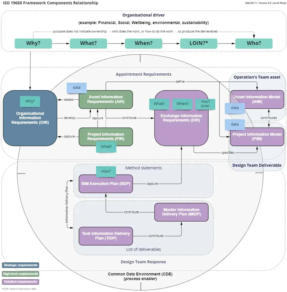
The transition from the BIM Levels to the concepts in the ISO 19650 series and the UK BIM Framework represents a shift in how we think about BIM maturity. However,

Guide to Visual Alarm Devices (VADs) in Fire Safety In high-noise workspaces or locations requiring hearing protection, Visual Alarm Devices (VADs) play a critical role in fire safety. They ensure

The term “Young Person” in the context of construction, Building Information Modeling (BIM), electrical engineering, or general engineering typically refers to a younger individual, often a recent graduate or entry-level

The term “X-ref” is commonly used as an abbreviation for “External Reference” in various technical and engineering fields, including construction, Building Information Modeling (BIM), and computer-aided design (CAD). Here’s a

part of indicating equipment which visually indicates the zone of origin of a alarm of fire or faultwarning BS 4422 2005 Zone Indicator in Fire Alarm Systems The zone indicator

nozzle reactionforce acting in the opposite direction to the water stream leaving the nozzle BS 4422 2005 “Jet reaction,” also known as “nozzle reaction,” is a fundamental concept in fluid

extinguishing medium, usually water, leaving a nozzle as a continuous stream, water spray, or waterfog (mist) BS 4422 2005 Each of these methods has its own advantages and is chosen
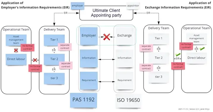
The Exchange Information Requirements (EIR) term introduced by BS EN 19650 replaces the PAS 1192 term Employer Information Requirements (EIR) on all projects where BS EN ISO 19650 compliance is
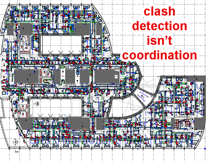
Coordination goes beyond orderly task execution, it transforms individual perspectives into shared, community-wide actions. It’s not just a subset of collaboration; it’s the engine that makes collaboration more than a patchwork of solo efforts.
That part of the earth fault loop impedance which is external to the circuit under consideration. For the supply cable it will be the impedance external to the installation. For
Z2 – That part of the earth fault loop impedance which comprises the impedance under earth fault conditions of the circuit protective conductor (cpc) of the circuit under consideration.
Z1 – That part of the earth fault loop impedance which comprises the impedance under earth fault conditions of the line conductor of the circuit under consideration.
An uninterruptible power supply (UPS) is used to maintain the supply to an essential service duringmains supply outages. On loss ofmains supply,a storage device in the UPS (battery) continues to
Uo Nominal line voltage to earth. Assumed to be 230 V for grid connected systems.
A system having one point of the source of energy directly earthed, the exposedconductive-parts of the installation being connected to earth electrodes electrically independent of the earth electrodes of the
A system having one or more points of the source of energy directly earthed, the exposedconductive-parts of the installation being connected to that point by protective conductors.
Where circuits are grouped, there are two availablemethods of calculating the rating factor Cg to be applied: [BS7671:2018,Appendix 4,5.1.2:Equation 2] [BS7671:2018,Appendix 4,5.1.2:Equation 3,4]
Relates to the ability of the soil, in which the cable is installed, to conduct heat energy away from the cable. The rating factor Cs is applied in cable sizing
AResidual Current Device (RCD) is amechanical switching device or association of devices intended to cause the opening of the contacts when the residual current* attains a given value under specified
Rating factors are divided into the nominal rating of the circuit protective device (In) to determine theminimum current-carrying capacity (Iz) of a cable in a circuit. For example:Iz = In/(Ca
Value of current used for specification purposes,established for a specified set of operating conditions.
Power factor is the ratio of the resistance (R) and impedance (Z) in a circuit, that is:Power factor = cos ∅ =R/Z
Themaximum value of earth fault loop impedance (Zs) that will allow the protective device in a circuit to disconnect an earth fault within the prescribed time. Example: if themaximum earth
Factors for conductor materials from BS7671:2018,Table43.1. Different values are given for different types of conductor and insulatingmaterials. k2s2 used in adiabatic calculations gives the short-time withstand of a conductor in
Iz The current carrying capacity of a cable under the defined installation conditions. This is the effective rating of the cable after the relevant rating factors have been applied, i.e.,Ca,
Ir The adjusted overload rating of an overcurrent protective device, in Amperes.