
“Electrical equipment shall be arranged to provide: 1. sufficient space for the initial installation and later replacement of individual items of electrical equipment; 2. accessibility for operation, inspection, testing, fault detection, maintenance and repair.”
Reference: BS 7671:2018+A4:2026, Regulation 132.12“Except for a joint in cables where Section 526 allows such a joint to be inaccessible, every item of equipment shall be arranged so as to facilitate its operation, inspection and maintenance and access to each connection. Such facility shall not be significantly impaired by mounting equipment in an enclosure or a compartment.”
Reference: BS 7671:2018+A4:2026, Regulation 513.1
There is no universal 1 m rule in UK law or in BS 7671. The legal duty is Regulation 15 of the Electricity at Work Regulations 1989, and the dimensions are in BS 7671 Section 729, the manufacturer’s instructions and client specifications such as WIMES 3.02. This guide covers switchrooms, distribution board positions and plant space in buildings in England.
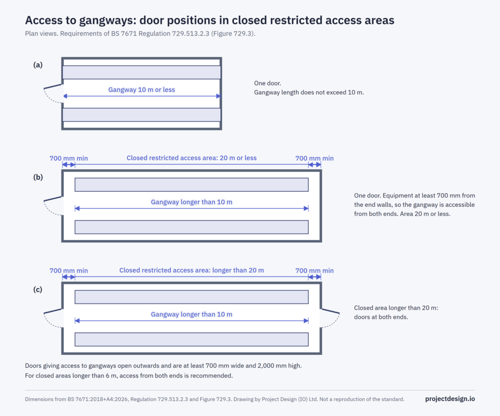
In restricted access areas (switchrooms, locked plant areas and roofs where access is restricted to skilled or instructed persons), BS 7671 Section 729 gives the minimum gangway dimensions and the conditions for operation and maintenance:
Where additional workspace is needed, for example for special switchgear and controlgear assemblies, larger dimensions may be required. [Regulation 729.513.2.1, Note]. The manufacturer’s instructions may require more than these minimums (see Manufacturer’s instructions below).
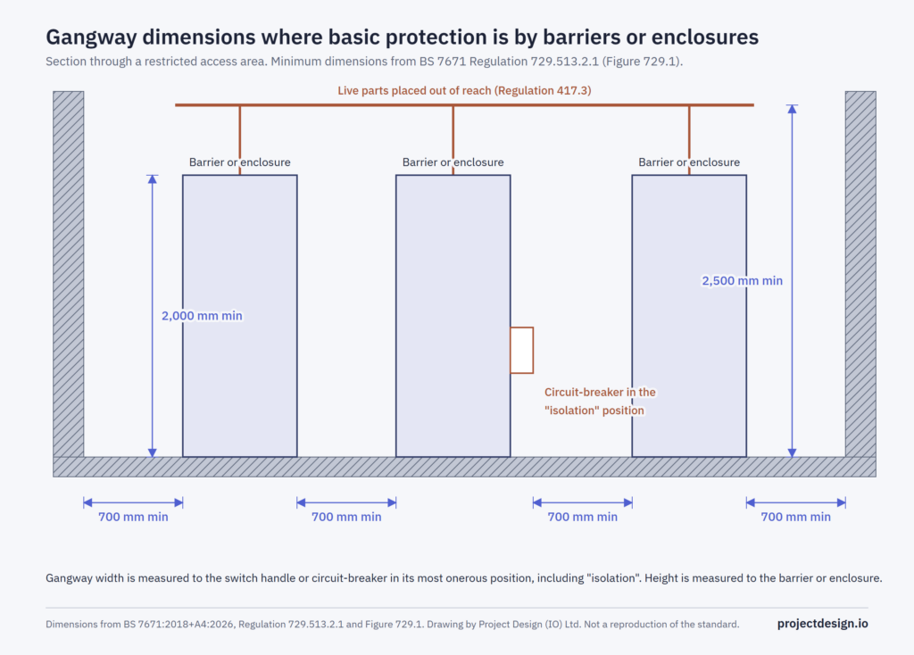
Corrected 23 September 2026: an earlier version of this section gave 900 mm, 1,100 mm and 1,300 mm gangway figures for exposed live parts. Those figures are not in BS 7671.
Consumer units and distribution boards in general access spaces: where a board is not in a restricted access area (a riser cupboard serving common parts, for example), Regulation 15 of the Electricity at Work Regulations 1989 and the manufacturer’s instructions set the working space and the reach to the means of isolation. BS 7671 gives no working depth for these positions. Apply the depth the manufacturer states. [Electricity at Work Regulations 1989, Regulation 15; BS 7671 Regulation 510.3]
In dwellings, Approved Document M gives the mounting height for equipment not intended for regular user interaction, such as meter cupboards and consumer units:
“Reasonable provision should be made to ensure that the approach route to any communal facilities that serve the dwelling meets these provisions. Communal facilities include storage areas, such as those used for depositing refuse and recycling, but not plant rooms or other service areas unless occupants need regular access, for example for meter reading.“
Reference: Approved Document M Volume 1 (2015 edition incorporating 2016 amendments), paragraph 2.4“Consumer units are mounted so that the switches are 1350-1450mm above floor level”
Reference: Approved Document M Volume 1, paragraph 1.18
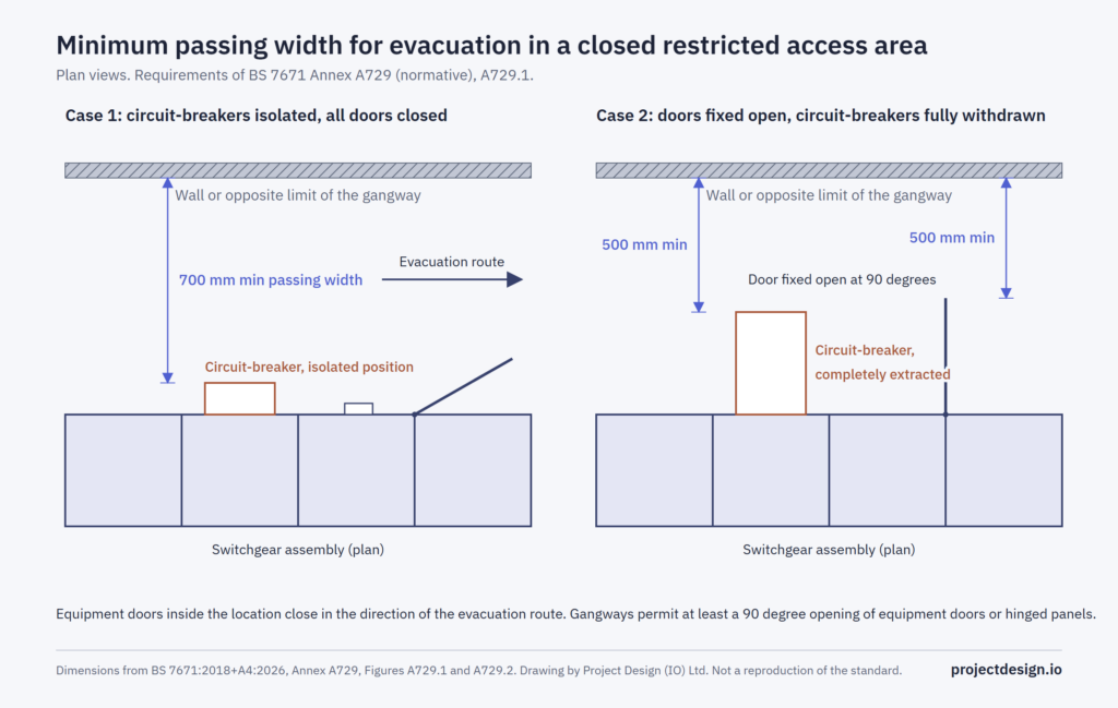
For easy evacuation, the doors of any equipment inside the location shall close in the direction of the evacuation route, and gangways shall permit at least a 90 degree opening of equipment doors or hinged panels. [BS 7671:2018+A4:2026, Annex A729 (normative), A729.1]
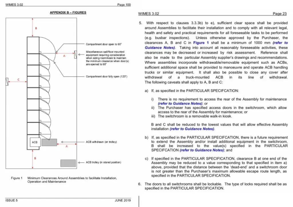
credit: Dan Oxford
The Water Industry Mechanical and Electrical Specifications (WIMES) 3.02, Low Voltage Electrical Installations, extends the BS 7671 gangway width to 1,000 mm:
“The minimum distance specified for the width of a maintenance gangway in Section 729 of BS 7671 is 700 mm, however, extending this to 1000 mm in this Specification is considered a reasonable measure to facilitate all foreseeable Assembly installation, operation and maintenance activities.”
Reference: WIMES 3.02 Low Voltage Electrical Installations, clause 3.3.5, quoted from an extract of the specification supplied by Dan Oxford. Check the clause against the WIMES issue current on your project.
Selection and erection shall take account of the manufacturer’s instructions. Where the manufacturer’s instructions or the project specification require a working depth of 1,000 mm or more in front of the assembly, that dimension is the project requirement, above the 700 mm minimum in BS 7671. Example: Schneider Electric FAQ FA32222. [BS 7671 Regulation 510.3]
Requirement B5 requires reasonable facilities to assist fire fighters and reasonable provision within the site for fire appliance access. Use it to coordinate plant room positions, switchgear access routes and external yard clearances. [Building Regulations 2010, Schedule 1, Requirement B5; Approved Document B Volume 2, Section 15]
Step 1: Classify the space
Step 2: Apply Part M
Step 3: Apply the manufacturer’s and the client’s requirements
Step 4: Egress and doors during maintenance
Step 5: Record the decision
Switchroom and plant space layouts are part of PD’s electrical design services.
Part B of the Building Regulations (England) sets the fire safety requirements for building work. Approved Document B gives the guidance in two volumes: Volume 1 for dwellings and Volume 2 for buildings other than dwellings.
The three tables below are Tables 2.3, 2.2 and 2.1 of Approved Document B Volume 2 (2019 edition incorporating 2020 and 2022 amendments). They apply to buildings other than dwellings. Other approaches may be valid: check with the project’s fire safety consultant and building control body.
| Maximum number of people | Minimum width |
|---|---|
| 60 | 750 mm |
| 110 | 850 mm |
| 220 | 1,050 mm |
| More than 220 | 5 mm per person |
| Minimum number of people | Minimum number of escape routes |
|---|---|
| 60 | 1 |
| 600 | 2 |
| more than 600 | 3 |
| Type of building | Maximum travel distance for escape available in one direction | Maximum travel distance for escape available in at least two directions |
|---|---|---|
| Residential (institutional) | 9 m | 18 m |
| Residential (other) in bedrooms [i] | 9 m | 18 m |
| Residential (other) in bedroom corridors [ii] | 9 m | 35 m |
| Residential (other) elsewhere | 18 m | 35 m |
| Offices | 18 m | 45 m |
| Shop and commercial premises | 18 m | 45 m |
| Assembly and recreation buildings primarily for disabled people | 9 m | 18 m |
| Assembly and recreation buildings with fixed seating in rows | 15 m | 32 m |
| Assembly and recreation buildings (elsewhere) | 18 m | 45 m |
| Industrial buildings, storage and other non-residential (normal hazard) [iii] | 25 m | 45 m |
| Industrial buildings, storage and other non-residential (higher hazard) [iii] | 12 m | 25 m |
| Place of special fire hazard [iv] | 9 m [v] | 18 m [v] |
| Plant room or rooftop plant (distance within the room) | 9 m | 35 m |
| Plant room or rooftop plant with escape route not in open air (overall travel distance) | 18 m | 45 m |
| Plant room or rooftop plant with escape route in open air (overall travel distance) | 60 m | 100 m |
Notes to Table 2.1:
[i] Maximum part of travel distance within the room. This limit applies within the bedroom and any associated dressing room, bathroom or sitting room, etc. The distance is measured to the door to the protected corridor that serves the room or suite.
[ii] Maximum part of travel distance applying from that point along the bedroom corridor to a storey exit.
[iii] The appropriate travel distance depends on the level of fire hazard associated with the processes and materials being used. For the definition of higher hazard, refer to Approved Document B Volume 2.
[iv] This is defined as a room such as an oil-filled transformer room, switch gear room, boiler room, storage space for fuel or other highly flammable substances or a room that houses a fixed internal combustion engine.
[v] Maximum part of travel distance within the room/area. Travel distance outside the room/area should comply with the limits for the purpose group of the building or part.
General note to Table 2.1:
If the internal layout of partitions, fittings, etc. is not known, direct distances, rather than travel distances, should be assessed. The direct distance should be assumed to be two-thirds of the actual travel distance.
Notes to Table 2.3:
Widths less than 1,050 mm should not be interpolated. The 5 mm per person figure does not apply to an opening serving fewer than 220 people. Widths may need to be increased to meet the guidance in Approved Document M.
The figures below are from BSRIA BG 84/2024, Figure 40 (space requirements and reach distances for installation and maintenance tasks). BSRIA bases the figure on BS 8313 as amended in BG 55.
Passageway:
Height: 2,100 mm minimum
Width: 550 mm minimum, 750 mm optimum
Maintenance reach levels:
Standing: 900 mm to 1.5 m
Kneeling: 600 mm
Sitting: 300 mm
Working postures (length by height):
Prone: 2.5 m by 450 mm
Crawl: 1.5 m by 790 mm
Squat: 690 mm by 1.2 m
Kneel: 1.1 m by 1.4 m
Stoop: 900 mm by 900 mm
Access routes:
Stairs: 600 mm to 750 mm for one person, 1.1 m minimum for two people
Ramps: 750 mm minimum, 1.1 m optimum, incline not to exceed 20 degrees
Ladders: 380 mm minimum, 450 mm optimum, 600 mm minimum between side walls
Source: BSRIA BG 84/2024, general building services section, Figure 40 and the access route figure that follows it.
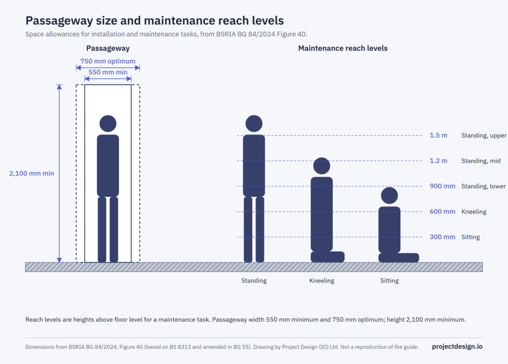
Image: BSRIA BG 84/2024, Figure 40 (based on BS 8313 and amended in BG 55).
During concept design and feasibility studies, use the BSRIA space and weight allowances to size plant rooms, coordinate structural loads and check access routes before the equipment is selected. The allowances in BSRIA BG 84/2024 give approximate space envelopes for common building services equipment, including maintenance access, concrete bases, cable and pipe clearances and heat dissipation zones.
Uses:
Note: these are preliminary allowances. Confirm them against the manufacturer’s datasheets, the detailed calculations and the current standards at detailed design.
The table below lists space allowances from BSRIA BG 84/2024, with the figure each one comes from. They are rules of thumb for early design, not requirements of any British Standard.
| Category | Equipment | Allowance type | Dimension | Location | Notes | Reference |
|---|---|---|---|---|---|---|
| Equipment Installation | Biomass Boilers | Base allowance | 150 mm | Below | Concrete base allowance | Figure 1 - Biomass boiler plant room area and height |
| Equipment Installation | Air Cooled Condensers | Base and anti-vibration mounts | 300 mm | Below | Base and anti-vibration mounts allowance | Figure 4 - Air cooled condensers area and height |
| Equipment Installation | Air Cooled Condensers | Heat dissipation clearance | Clear height required | Above | Clear height above units must be provided for vertical air discharge to allow heat to dissipate | Figure 4 - Air cooled condensers area and height |
| Equipment Installation | Air Handling Units | Base and condensate trap | 200 mm | Below | Base and condensate trap allowance | Figure 6 - Air handling units area and height |
| Equipment Installation | Air Handling Units | Crawl space above unit | 790 mm | Above | Crawl space above each unit for maintenance access | Figure 6 - Air handling units area and height |
| Equipment Installation | Gas Fired Boilers | Base allowance | 150 mm | Below | Concrete base allowance | Figure 8 - Gas fired boiler plant room area and height |
| Equipment Installation | Horizontal Calorifiers | Base allowance | 100 mm | Below | Concrete base allowance | Figure 10 - Horizontal calorifiers area and height |
| Equipment Installation | Horizontal Calorifiers | Pipework clearance | 1,000 mm | Above | Height allowance for pipework | Figure 10 - Horizontal calorifiers area and height |
| Equipment Installation | Vertical Calorifiers | Base allowance | 100 mm | Below | Concrete base allowance | Figure 12 - Vertical calorifiers area and height |
| Equipment Installation | Vertical Calorifiers | Pipework clearance | 1,000 mm | Above | Height allowance for pipework | Figure 12 - Vertical calorifiers area and height |
| Equipment Installation | Air Cooled Chillers | Base and anti-vibration mounts | 300 mm | Below | Base and anti-vibration mounts allowance | Figure 14 - Air cooled chillers area and height |
| Equipment Installation | Air Cooled Chillers | Heat dissipation clearance | Clear height required | Above | Clear height above units must be provided for vertical air discharge to allow heat to dissipate | Figure 14 - Air cooled chillers area and height |
| Equipment Installation | Water Cooled Chillers | Base and anti-vibration mounts | 300 mm | Below | Concrete base and anti-vibration mounts allowance | Figure 16 - Water cooled chillers area and height |
| Equipment Installation | Forced Draught Cooling Towers | Base allowance | 200 mm | Below | Base allowance for foundation | Figure 18 - Forced draught cooling tower area and height |
| Equipment Installation | Forced Draught Cooling Towers | Heat dissipation clearance | Clear height required | Above | Clear height above units for vertical air discharge to allow heat to dissipate | Figure 18 - Forced draught cooling tower area and height |
| Equipment Installation | Induced Draught Cooling Towers | Base allowance | 200 mm | Below | Base allowance for foundation | Figure 20 - Induced draught cooling tower area and height |
| Equipment Installation | Induced Draught Cooling Towers | Heat dissipation clearance | Clear height required | Above | Clear height above units for vertical air discharge to allow heat to dissipate | Figure 20 - Induced draught cooling tower area and height |
| Equipment Installation | Cold Water Storage Tanks | Base allowance | 150 mm | Below | Concrete base allowance | Figure 22 - Cold water storage area and height |
| Equipment Installation | Cold Water Storage Tanks | Freeboard height | 500 mm | Above water level | Freeboard height allowance above maximum water level | Figure 22 - Cold water storage area and height |
| Equipment Installation | Cold Water Storage Tanks | Crawl space above tank | 790 mm | Above | Crawl space above tank for maintenance access | Figure 22 - Cold water storage area and height |
| Equipment Installation | Cold Water Storage Tanks (External Flange) | Additional height for external flange | 500 mm | Above | Additional height allowance if externally flanged tank is used | Figure 22 - Cold water storage area and height |
| Equipment Installation | Diesel Generators | Base and anti-vibration mounts | 300 mm | Below | Concrete base and anti-vibration mounts allowance | Figure 24 - Diesel generators area and height |
| Equipment Installation | Diesel Generators | Crawl space above unit | 790 mm | Above | Crawl space above unit for maintenance access | Figure 24 - Diesel generators area and height |
| Equipment Installation | Hybrid Rotary UPS | Base allowance | 100 mm | Below | Concrete base allowance | Figure 26 - Hybrid rotary UPS area and height |
| Equipment Installation | Hybrid Rotary UPS | Cable installation height | 1,000 mm | Above | Height allowance for cable installation | Figure 26 - Hybrid rotary UPS area and height |
| Equipment Installation | Static UPS | Cable installation space | Additional space required | Top and bottom | Additional space should be provided at top and bottom for cable installation | Figure 28 - Static UPS area and height |
| Equipment Installation | Static UPS (≥400 kVA) | Cooling clearance | 400 mm | Above | Additional clearance at top for cooling purposes for UPS rated 400 kVA or above | Figure 28 - Static UPS area and height |
| Equipment Installation | Static UPS | Rear cooling space | Per manufacturer specifications | Behind | Additional space for cooling at rear in accordance with manufacturer specifications | Figure 28 - Static UPS area and height |
| Equipment Installation | Packaged Substations | Base allowance | 100 mm | Below | Concrete base allowance | Figure 30 - Packaged substations area and height |
| Equipment Installation | Packaged Substations | Crawl access space | 790 mm | Above | Crawl access space above unit for maintenance | Figure 30 - Packaged substations area and height |
| Equipment Installation | UPS Battery Racks | Maximum safe height | 2,000 mm maximum | Above floor | For safe access to battery rack, height should not exceed 2 m | Figure 32 - UPS battery rooms area and height |
| Equipment Installation | LV Switch Rooms (up to 750 kVA) | Cable installation height | 1,000 mm | Above | Height allowance for cable installation for ratings up to 750 kVA | Figure 34 - Switch rooms area and height |
| Equipment Installation | LV Switch Rooms (≥1,000 kVA) | Cable installation height | 1,500 mm | Above | Height allowance for cable installation for ratings 1,000 kVA and above | Figure 34 - Switch rooms area and height |
| Equipment Installation | LV Switch Rooms | Base allowance | 100 mm | Below | Concrete base allowance | Figure 34 - Switch rooms area and height |
| Equipment Installation | Transformers | Base allowance | 100 mm | Below | Concrete base allowance | Figure 36 - Transformers area and height |
| Equipment Installation | Transformers | Cable installation height | 1,000 mm | Above | Height allowance for cable installation | Figure 36 - Transformers area and height |
| Maintenance Access | Switchgear | Operating and maintenance gangways | 700 mm minimum | All sides | Gangways should permit at least 90° opening of equipment doors or hinged panels | Figure 38 - Switchgear space for operating and maintenance (Based on BS 7671) |
| Safety | Switchgear | Safety clearance from live parts | 2,000 mm height, 2,500 mm overall | Above and around live parts | For placing electrical equipment out of reach per BS 7671 Regulation 417.3 | Figure 38 - Switchgear space for operating and maintenance (Based on BS 7671) |
| Building Services | Ceiling Voids - Structural | Structural deflection | 50 mm | Above structural elements | Allowance for structural deflection plus tolerance | Figure 39 - Ceiling and floor voids in a generic office building |
| Building Services | Ceiling Voids - Sprinkler | Sprinkler zone | 50 mm + 150 mm | Above other services | Clearance zone for sprinkler systems | Figure 39 - Ceiling and floor voids in a generic office building |
| Building Services | Ceiling Voids - Lighting | Lighting zone | 150 mm | Below ceiling | Zone allocation for lighting installations | Figure 39 - Ceiling and floor voids in a generic office building |
| Building Services | Ceiling Voids - Luminaires | Luminaire removal clearance | 1.5 times luminaire height | Around luminaires | Clearance to facilitate removal of lighting fittings and heat dissipation | Figure 39 - Ceiling and floor voids in a generic office building |
| Building Services | Ceiling Voids | Ceiling deflection | 50 mm | Below ceiling | Allowance for ceiling deflection | Figure 39 - Ceiling and floor voids in a generic office building |
| Building Services | Floor Voids - Office | Typical office access | 150 mm minimum | Under raised floor | Minimum access space under raised floors for typical offices | Figure 39 - Ceiling and floor voids in a generic office building |
| Building Services | Floor Voids - Trading Floor | Trading floor access | 300-500 mm | Under raised floor | Enhanced access space for trading floors | Figure 39 - Ceiling and floor voids in a generic office building |
| Building Services | Access Panels | Minimum panel size | 600 mm x 600 mm minimum | Multiple locations | Minimum size for access panels throughout building services | Figure 39 - Ceiling and floor voids in a generic office building |
| Building Services | Terminal Units | Maintenance access | 500 mm minimum | Around terminal units | Clear access to terminal units for maintenance | Figure 39 - Ceiling and floor voids in a generic office building |
| Maintenance Reach | Standing Maintenance Work | Maximum reach height | 2,100 mm maximum | Above floor level | Maximum height for safe standing maintenance access | Figure 40 - Space requirements and reach distances (Based on BS 8313 amended in BG 55) |
| Maintenance Reach | Prone Maintenance Work | Minimum height for prone access | 450 mm | Height clearance | Minimum height required for prone maintenance position | Figure 40 - Space requirements and reach distances (Based on BS 8313 amended in BG 55) |
| Maintenance Reach | Crawl Maintenance Work | Minimum height for crawling | 900 mm | Height clearance | Minimum height required for crawling maintenance access | Figure 40 - Space requirements and reach distances (Based on BS 8313 amended in BG 55) |
| Maintenance Reach | Stooping Maintenance Work | Minimum height for stooping | 900 mm | Height clearance | Minimum height required for stooping maintenance work | Figure 40 - Space requirements and reach distances (Based on BS 8313 amended in BG 55) |
| Maintenance Reach | Squatting Maintenance Work | Minimum height for squatting | 690 mm | Height clearance | Minimum height required for squatting maintenance position | Figure 40 - Space requirements and reach distances (Based on BS 8313 amended in BG 55) |
| Maintenance Reach | Kneeling Maintenance Work | Minimum height for kneeling | 1,100 mm | Height clearance | Minimum height required for kneeling maintenance work | Figure 40 - Space requirements and reach distances (Based on BS 8313 amended in BG 55) |
| Access Routes | Passageway - Single Person | Width | 550 mm minimum, 750 mm optimum | Width | Width requirement for single person passage | Figure 40 - Space requirements and reach distances (Based on BS 8313 amended in BG 55) |
| Access Routes | Ladder | Width | 380 mm minimum, 450 mm optimum | Width | Ladder width requirements for safe access | Page 48 - Access route clearances (Based on BS 8313 amended in BG 55) |
| Access Routes | Ladder | Side clearance | 600 mm minimum | Between side walls | Clear space required around ladder between side walls | Page 48 - Access route clearances (Based on BS 8313 amended in BG 55) |
| Access Routes | Inclined Ladder | Width with handrails | 530-600 mm | Width including handrails | Width including handrails for inclined ladders | Page 48 - Access route clearances (Based on BS 8313 amended in BG 55) |
| Access Routes | Stairs - Single Person | Width | 600-750 mm | Width | Width for single person stair access | Page 48 - Access route clearances (Based on BS 8313 amended in BG 55) |
| Access Routes | Stairs - Two Person | Width | 1,100 mm minimum | Width | Width for two people on stairs simultaneously | Page 48 - Access route clearances (Based on BS 8313 amended in BG 55) |
| Access Routes | Ramp | Width | 750 mm minimum, 1,100 mm optimum | Width | Ramp width requirements for safe access | Page 48 - Access route clearances (Based on BS 8313 amended in BG 55) |
| Access Routes | Ladder Rungs | Rung spacing and diameter | 180-406 mm spacing, 20-40 mm diameter | Vertical spacing and rung size | 300 mm optimum spacing, standard rung diameter range | Page 48 - Access route clearances (Based on BS 8313 amended in BG 55) |
| Access Routes | Stair Treads and Risers | Tread and riser dimensions | 240 mm optimum tread, 250 mm maximum riser | Stair geometry | Optimum tread depth and maximum riser height for safety | Page 48 - Access route clearances (Based on BS 8313 amended in BG 55) |









2 responses
Hey Jarek, just reading your latest post about clearance rules.
Your 100% correct you won’t find a blanket 1,000 mm clearance rule written into UK legislation or BS 7671 as far as I’m aware.
Exactly as you said, Legislation / ADB / HSG85 / CDM all talk about providing safe access, safe working space, and designing out maintenance risks, but none of them give a fixed measurement.
My work is mainly in the water industry, and this is where the 1 m clearance does appear – but only in sector or client specifications, not in the regs. The water industry standard WIMES 3.02 calls for 1 m clearance around LV assemblies so you can open doors properly, withdraw ACBs for normal operation and maintenance, and provide safe escape in an emergency.
Let me know if you find anything.
Thanks,
Dan
Thanks, Dan — really appreciate you sharing the water-industry context. I’ve updated the post thanks to you.